Friday, June 02, 2006
Godzilla z-axis is WIRED!
I finished installing pulleys and cables on the Godzilla z-axis (horizontal) this morning. 
While installing the right-hand pulleys I discovered that by flipping the bottom, right-hand pulley I could shift the top, right-hand pulley to the left of the drive cable and avoid having to have the cable cross itself as is shown in my last blog sketch. That worked beautifully.
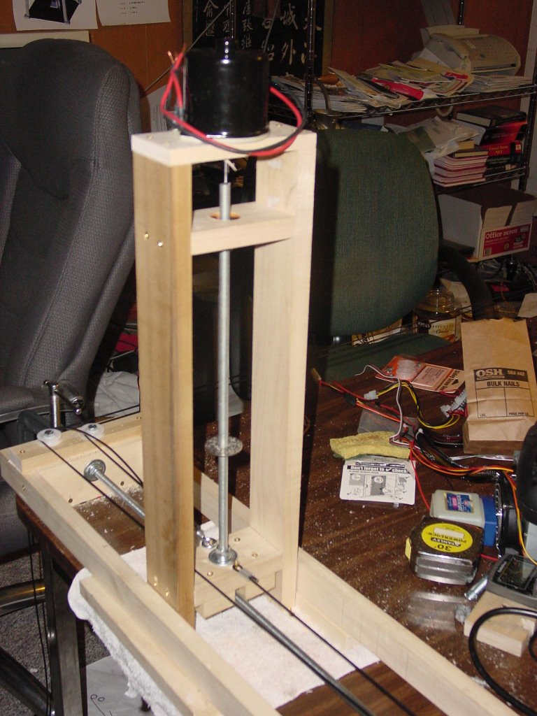
Here is the left-hand, powered z-axis positioning stage. The cable ends are secured on a plane shared by both the z-axis threaded drive rod and the y-axis threaded drive rod.
Pardon the tilt on the pic of the right hand z-axis positioning stage. Again you can see that the drive cable runs on a line with the threaded drive rod. You can note that I've already removed the unnecessary y-axis threaded drive rod. The z-axis rod remains in this picture only because I needed it to line up the cable. In operation the right-hand, z-axis threaded drive rod will be removed as well.
Here is a detail of the far side of the right-hand, z-axis positioning stage showing the transfer pulleys and change I made in the cable layout to avoid having to cross the cables. You can also see how I secured the cable to the right-hand y-axis tower with a grooved block of poplar fastened with one of the ubiquitous c-clamps.
Finally, here is a detail of the cable attachment to the left-hand y-axis tower. I've put a simple turnbuckle to control the cable tension. I also discovered that you have to be careful to completely crush the cable ferrules onto the cable with a vise rather than using a pair of pliers.
I filmed two short movies of the y-axis towers moving in concert. Looking at them I can see that the company Sony digital camera is, after seven years, seriously out of date when compared to movie quality that my son's little Kodak delivers. The upside of that is that my son's Kodak cost a fraction of what we originally paid for the Sony. :-)
I beg your pardon in advance for the erratic filming of Godzilla in these two clips. I was having to film and run the drive control switch by myself, my son having returned to university. :-(
http://www.sanma12.com/RepRap/z-axis wired 01.mpg
http://www.sanma12.com/RepRap/z-axis wired 02.mpg
The right-hand z-axis positioning stage is a little tight and is adding considerable friction to the ensemble. A bit of sanding should set that right, though. :-)
Right now I'm rebuilding the powered, left-hand y-axis tower.
I guess that I'm going to have to seat the rotary shaft encoder down in the pocket between the bottom of the threaded y-axis drive just above the coup nut thrust collar of the z-axis threaded drive rod. It's going to be a little tight in there.

While installing the right-hand pulleys I discovered that by flipping the bottom, right-hand pulley I could shift the top, right-hand pulley to the left of the drive cable and avoid having to have the cable cross itself as is shown in my last blog sketch. That worked beautifully.
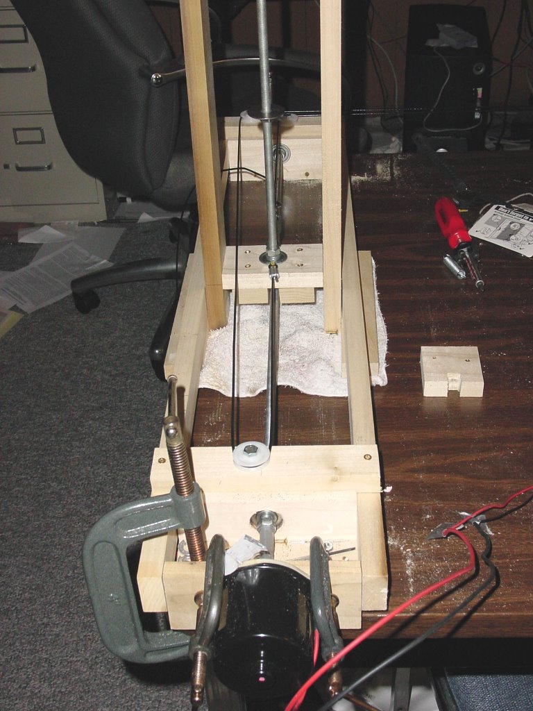
Here is the left-hand, powered z-axis positioning stage. The cable ends are secured on a plane shared by both the z-axis threaded drive rod and the y-axis threaded drive rod.
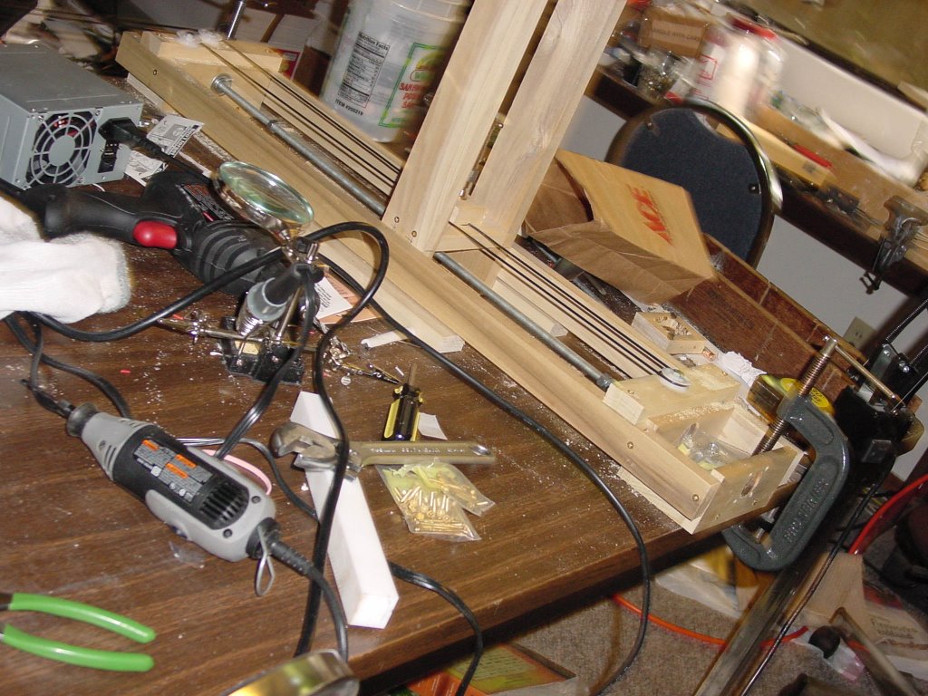
Pardon the tilt on the pic of the right hand z-axis positioning stage. Again you can see that the drive cable runs on a line with the threaded drive rod. You can note that I've already removed the unnecessary y-axis threaded drive rod. The z-axis rod remains in this picture only because I needed it to line up the cable. In operation the right-hand, z-axis threaded drive rod will be removed as well.
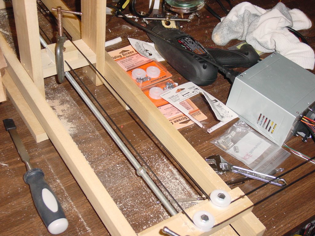
Here is a detail of the far side of the right-hand, z-axis positioning stage showing the transfer pulleys and change I made in the cable layout to avoid having to cross the cables. You can also see how I secured the cable to the right-hand y-axis tower with a grooved block of poplar fastened with one of the ubiquitous c-clamps.
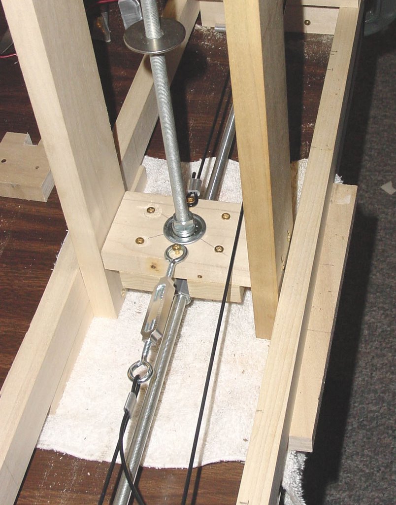
Finally, here is a detail of the cable attachment to the left-hand y-axis tower. I've put a simple turnbuckle to control the cable tension. I also discovered that you have to be careful to completely crush the cable ferrules onto the cable with a vise rather than using a pair of pliers.
I filmed two short movies of the y-axis towers moving in concert. Looking at them I can see that the company Sony digital camera is, after seven years, seriously out of date when compared to movie quality that my son's little Kodak delivers. The upside of that is that my son's Kodak cost a fraction of what we originally paid for the Sony. :-)
I beg your pardon in advance for the erratic filming of Godzilla in these two clips. I was having to film and run the drive control switch by myself, my son having returned to university. :-(
http://www.sanma12.com/RepRap/z-axis wired 01.mpg
http://www.sanma12.com/RepRap/z-axis wired 02.mpg
The right-hand z-axis positioning stage is a little tight and is adding considerable friction to the ensemble. A bit of sanding should set that right, though. :-)
Right now I'm rebuilding the powered, left-hand y-axis tower.
I guess that I'm going to have to seat the rotary shaft encoder down in the pocket between the bottom of the threaded y-axis drive just above the coup nut thrust collar of the z-axis threaded drive rod. It's going to be a little tight in there.
Comments:
<< Home
Looking forward to seeing how this motor and pulley arrangement performs!
I guess pulling all the slack you can out of it is important to reducing the delay in movement between the one half with the motor and the other half without...?
I guess pulling all the slack you can out of it is important to reducing the delay in movement between the one half with the motor and the other half without...?

***Looking forward to seeing how this motor and pulley arrangement performs!***
It performs wonderfully! :-)
***I guess pulling all the slack you can out of it is important to reducing the delay in movement between the one half with the motor and the other half without...?***
That's exactly right. It only happens in the z-axis cabling, though. The tradeoff is making it tight enough to minimise that tendency for the powered side to "wag" the unpowered side without tightening it so much that there is so much friction in the system that your drive motor's power consumption becomes unreasonable.
Actually though, if we are going to map inaccuracies with a digital calibration approach the nature and magnitude of that "wag" is VERY predictable. As long as you're not extruding while the wag is taking place, which is a matter of a fraction of a millimeter you should be good to go.
Post a Comment
It performs wonderfully! :-)
***I guess pulling all the slack you can out of it is important to reducing the delay in movement between the one half with the motor and the other half without...?***
That's exactly right. It only happens in the z-axis cabling, though. The tradeoff is making it tight enough to minimise that tendency for the powered side to "wag" the unpowered side without tightening it so much that there is so much friction in the system that your drive motor's power consumption becomes unreasonable.
Actually though, if we are going to map inaccuracies with a digital calibration approach the nature and magnitude of that "wag" is VERY predictable. As long as you're not extruding while the wag is taking place, which is a matter of a fraction of a millimeter you should be good to go.
<< Home
![]()