Thursday, June 15, 2006
First crude attempts at calibration...
I've been worried that the unpowered side of the z-axis platform might be lagging behind the powered side, creating a wag. I tried measuring this yesterday by marking one the near edge of both y-axis towers on their guide bar and do it when the z-axis moves out and marking it again when it came back. The wag should have been half of the difference between the gap on the unpowered side minus the gap on the powered side.
That exercise seemed to show about a 1.2 mm wag. I tightened the z-axis cables after that and the wag seemed to have gone away.
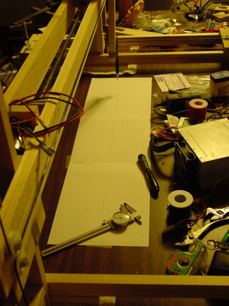
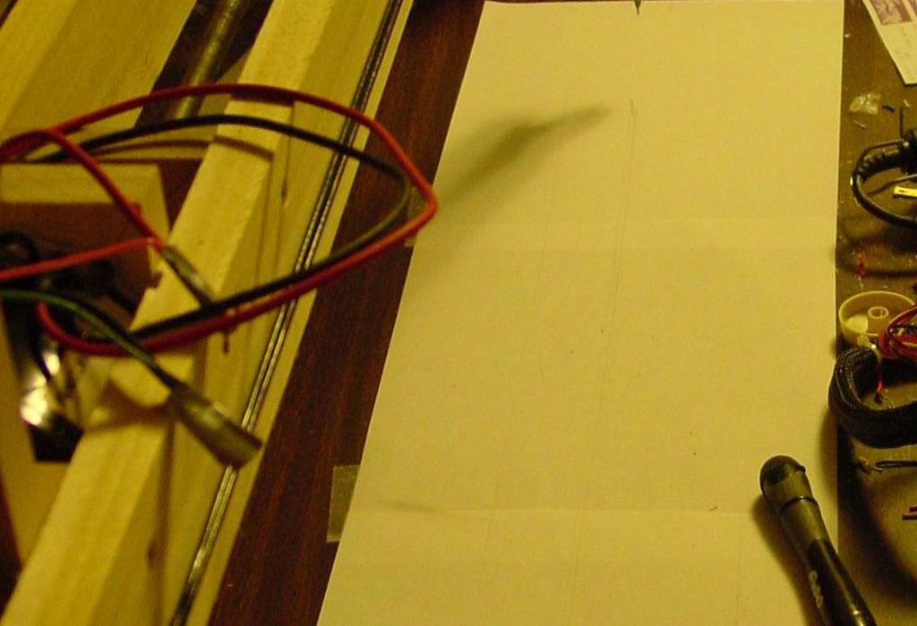
This evening I decided to take a more direct approach, so I just taped down several sheets of typing paper and taped a mechanical pencil to the x-axis platform. I then drew a line from the powered side to the unpowered side when the z-axis platform had been moving out and again when I moved it back, capturing both sides of the wag. I then used my calipers to measure the distance between the lines at either end to calculate the wag.
The wag seemed to be less than the 0.5 mm width of the pencil line, which is to say, unmeasureable.
I had the idea today that if I put limits switches on both sides of the z-axis platform that ought, along with information from the rotary encoder, to be enough data to develop correction coefficients for the z-axis.
I also disassembled the z-axis to see how much play was in the coupling nut. Interestingly, there is very little if any play along the axis of of the threaded rod. The nut can, however, be rattled in position on the threaded rod slightly. It's not an antibacklash fitting, but it's not bad.
One thing that I did spot is that I have a bit of vibration in the x-axis platform. The mechanical pencil faithfully recorded it like my very own little seismograph. The amplitude of the vibration was about 0.64 mm. I am going to have to smooth out the action of the x-axis platform a bit. That shouldn't be too difficult.
I ran a similar test with the z-axis looking for vibration. There was no visible vibration in the z-axis translation.
UPDATE ON X-AXIS VIBRATION: A little block of PTFE taped onto the vertical pencil mounting block serving as a guide on the x-axis side bar got rid of about 90% of the vibration at the mechanical pencil point. It will be very easy to sort out.
That exercise seemed to show about a 1.2 mm wag. I tightened the z-axis cables after that and the wag seemed to have gone away.
This evening I decided to take a more direct approach, so I just taped down several sheets of typing paper and taped a mechanical pencil to the x-axis platform. I then drew a line from the powered side to the unpowered side when the z-axis platform had been moving out and again when I moved it back, capturing both sides of the wag. I then used my calipers to measure the distance between the lines at either end to calculate the wag.
The wag seemed to be less than the 0.5 mm width of the pencil line, which is to say, unmeasureable.
I had the idea today that if I put limits switches on both sides of the z-axis platform that ought, along with information from the rotary encoder, to be enough data to develop correction coefficients for the z-axis.
I also disassembled the z-axis to see how much play was in the coupling nut. Interestingly, there is very little if any play along the axis of of the threaded rod. The nut can, however, be rattled in position on the threaded rod slightly. It's not an antibacklash fitting, but it's not bad.
One thing that I did spot is that I have a bit of vibration in the x-axis platform. The mechanical pencil faithfully recorded it like my very own little seismograph. The amplitude of the vibration was about 0.64 mm.
 I am going to have to smooth out the action of the x-axis platform a bit. That shouldn't be too difficult.
I ran a similar test with the z-axis looking for vibration. There was no visible vibration in the z-axis translation.
UPDATE ON X-AXIS VIBRATION: A little block of PTFE taped onto the vertical pencil mounting block serving as a guide on the x-axis side bar got rid of about 90% of the vibration at the mechanical pencil point. It will be very easy to sort out.
Comments:
<< Home
I'd been wondering about that very same "lag wag" issue. Glad to see it seems to be under control. I'm hoping there won't be a bit of curvature (hump or sag) in the long span of wood between the towers that might throw off the thickness of the first layer you would deposit. If there was, it could be solved in a number of simple ways I think, like laying an innert pad of extrudate as a base on which to start fabrication of the actual part. If the base pad of extrudate had a curve, it would be shallow and might not affect the part's usefullness...
Little parts wouldn't even register the curve.
At the same time, maybe this pad would smooth out the assorted variations of alignment between the different axis and the base or table Godzilla is on.
Now I'm just hoping that given there is no gear slack, those big motors will give the needed accuracy without too much fuss. :)
In the mean time, seeing Vic's evolving CAPAgons, I'm tempted to experiment with that fussy HDPE stuff...
Potential new term: RepScrap - Bit's and pieces of innocent matter that get assembled, mashed, and otherwise sacrificed in the process of attempting to build a RepRap machine...
Post a Comment
Little parts wouldn't even register the curve.
At the same time, maybe this pad would smooth out the assorted variations of alignment between the different axis and the base or table Godzilla is on.
Now I'm just hoping that given there is no gear slack, those big motors will give the needed accuracy without too much fuss. :)
In the mean time, seeing Vic's evolving CAPAgons, I'm tempted to experiment with that fussy HDPE stuff...
Potential new term: RepScrap - Bit's and pieces of innocent matter that get assembled, mashed, and otherwise sacrificed in the process of attempting to build a RepRap machine...

<< Home
![]()