Monday, May 15, 2006
Thoughts on scaleable RepRaps...
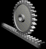 Now that we can make involute profile gears, why don't we make racks to go with them?
If you split the rack lengthwise and made it in sections of maybe 200 mm it would be relatively easy to design a sliding dovetail connection so that two lengths could be assembled to make one rack twice as wide. Stagger these sections and you could make a rack as long as you desired from 200 mm sections.
Put holes in the sections that were a little wider than the bolt that went through them. Reprap an alignment template jig so that you could hold the two halves together while you secured them with nuts, bolts and lock washers and you are good to go.
Lay a printed linear encoder strip beside your rack and you have a track that a positioning stage can use.
A bunch of things have been bothering me lately. We've got good control boards for steppers and we've got good steppers with magnificent angular resolution. Unfortunately, stepper torque drops like a stone when you try to run them quickly. We stick these onto threaded rod drives like we see our CNC hobbyist friends using. These guys are running their systems very slowly because they are doing things like cutting patterns in a piece of wood with a router. When you are doing that sort of thing speed is not what you want, so steppers work magnificently.
We're not taking away material, though. We're laying it down. Our productivity depends on how fast we can extrude material. The Mk II extruder currently operates at 4 mm/sec. At a 50% duty cycle it will put down 1 kg of polymer/month. We need to be doing five times that to have a viable system. The current Mk II technology can probably be pushed into doing that by putting more energy into the extruder head and amping up the feed.
Our current positioning stages are more of a problem, however. We can do about 1 rps with our steppers. Using threaded rod positioning systems that means we can move about 1 mm/sec. If we try to go a lot faster than that our torque goes away. We need to be doing twenty times that.
The problem isn't with our control theory or with the steppers. Those are fine. The problem is the use of threaded rods for positioning. Threaded rods are fine for the vertical axis. Speed isn't an issue there. For the horizontal axes, however, they don't work all that well.
Why not rack and pinion?
Most of the CNC equipment that I've seen uses rack and pinion. If we were to use our existing steppers to drive rack and pinion positioning we could get the speed we need without a lot of drama and without trying to make our control boards do things they were never intended to do.
We're not trying to carve anything so our positioning systems can be light. Ed's string machine had a lot going for it in terms of using the method for keeping things aligned while applying force asymetrically. I think where the trouble began is when he tried to apply motive force to the cables. In Godzilla it would be relatively easy to use drafting board cable and pully technology to reduce the number of steppers needed and the complexity of the control system.
Now that I can design gears I'm probably just seeing everything as problems with gear problems. :-p
Comments:
<< Home
Oh yeah, baby!
That's a damn fine idea. I think we've all been thinking they're the likely tool needed to eliminate threaded rod in the future.
That's a damn fine idea. I think we've all been thinking they're the likely tool needed to eliminate threaded rod in the future.

Outstanding!
Rack and pinion drive would be fine, but you can't also use it as the bearing "surface" for movement - too bumpy.
Rack and pinion drive would be fine, but you can't also use it as the bearing "surface" for movement - too bumpy.
The hobbyist CNC tools that I've seen always have the rack pointing teeth downward off the side of their work surfaces.
//The Mk II extruder currently operates at 4 mm/sec. At a 50% duty cycle it will put down 1 kg of polymer/month. We need to be doing five times that to have a viable system.//
Thoughts that come to mind:
1. multiple heads working in parallel
2. a dual head system with a narrow extruder for all the fiddly bits and a fat extruder for large fills
3. a variable aperture (and flow rate) extruder
4. a system that places pre-molded pieces of plastic (e.g. squares, circles, hexagons) and uses the extruder to join the pieces and add on any fiddly bits
* 1kg/month isn't very good at all. What's our target weight for the reprap right now? 2kg?
* I vote for parallel heads or *maybe* fine head and roughing head system. The advantage of parallel heads is we can still print at all parts of the table - if we have a fine head and roughing head 1 cm apart, then we can't rough fill on the left cm of the table and we can't fine fill on the right.
* A variable aperture extruder will require a mechanical acturator for the extruder tip, one we can't reprap.
* Placing pre-moulded pieces on the table requires a little 3 DOF pick and place robot with .1m accuracy, a feeding hopper, a welding tip, and a pre-moulded piece making machine.
* What about .5mm circular fine head and a 0.5mm x 5.0 slit head that puts down a 0.5 by 5.0 thick ribbon?
* MkII is an early test extruder. It is likely to go a fair bit faster in future. The intention is to get the principles right then make it go faster.
* It probably still won't be fast enough, and we'll always want it to be faster.
* Multiple nozzles (inkjet printer approach)... interesting idea! Bulk nozzles are good too, but a ribbon nozzle is slightly tricky because you have to move it in the right direction -- which is no real problem I guess if you're just filling.
* We have previously talked about using a bulk filler (eg pouring cement and letting it set) and only creating the exterior framing with plastic. There are ideas like using a head carousel to exchange the current extruder like a plotter changes a pen so the software is designed around having multiple extruders and materials.
Eventually we will need a multihead system to do PC boards. One with a conductive material and another with the standard (insulating) material.
I know it is yet another method, but taking another queue from the CNC arena, how about 'changable tools'. We could change entire heads (designed for fast/high volume/low-fidelity extrusion, fine/high-fidelity/low volume extrusion, conductive [nearer the fine/high-fidelity], 3d scanner head with or without probe, etc.) - or possibly changing tips for various types of extrusions.
I know it is yet another method, but taking another queue from the CNC arena, how about 'changable tools'. We could change entire heads (designed for fast/high volume/low-fidelity extrusion, fine/high-fidelity/low volume extrusion, conductive [nearer the fine/high-fidelity], 3d scanner head with or without probe, etc.) - or possibly changing tips for various types of extrusions.
What about a fine 0.5 head mm, an x ribbon head thats 0.5*5.0 mm, and a y ribbon head that's 5.0*0.5 mm?
We use the x ribbon head for bulk fill on the odd layers, and a y ribbon head for bulk fill on the even layers. I like ribbons more than thick tube because a ribbon sticking to another ribbon is a stronger bond than a cylinder sticking to another cylinder. A circular bulk 3mm bulk fill head used every 6 layers isn't going to bond to the fine filaments very well, necessarily.
* ***
* ******
**********
**********
* ******
* ***
We have to use a fine head to print the outside surfaces. The outside surfaces are where all the wear and tear starts. If the fine filaments separate from the bulk fill due to lousy bonding, the outer sheath falls off, and we're left with a hairy block.
You could manufacturing a ribbon head usinging a mill or drill press with milling table, and drill it out, then dress with a needle file or strip of sand paper.
Or photo etch a rectangle with a slot in it and two bolt holes, and then bolt the rectangle or a stack of rectangles onto the tip of the extruder.
I'm shooting for just amping up Mk II to run at 20 mm/sec and creating a positioning system that can accomodate that. That will give us 5 kg of polymer put down a month. To give you an idea of scale that's over 700 metres of 3 mm filament. That's also roughly US$100 worth of polymer/month.
The way I look at it is that at that level of production if you want to get more production, simply task your RepRap to make another RepRap.
I think we'll need a couple of heads; one for polymer and another for support material, be it confectioner's sugar or overfilled polymer.
The way I look at it is that at that level of production if you want to get more production, simply task your RepRap to make another RepRap.
I think we'll need a couple of heads; one for polymer and another for support material, be it confectioner's sugar or overfilled polymer.
Damn, the webpage ate my spaces.
Imagine a stack of fine filaments, with a parallel thick filament bonded center of the stack, but not to the top and bottom fine filaments.
We want bulk fill/muliheads soon, or the reprap is only useful for patient people. "What, it takes a month to make anything big? Screw that."
Imagine a stack of fine filaments, with a parallel thick filament bonded center of the stack, but not to the top and bottom fine filaments.
We want bulk fill/muliheads soon, or the reprap is only useful for patient people. "What, it takes a month to make anything big? Screw that."
I love all these suggestions for improving the machine, and they're all being preserved. But we're improving something that doesn't exist. Yet.
Priority is not to make it fast, nor to make it accurate, nor to make it reliable. Priority is to make it work.
THEN we do all the rest.
BUT - keep the suggestions coming, folks :)
And don't worry about repeating something someone else said in February - the frequency with which a suggestion comes up may be a measure of its importance.
For example the idea of a rough and a fine head has been mentioned several times. The (soluble) problem there is that the rough head produces a deeper extrusion as well as a wider one. But that can be designed out.
I'd vote for still running on precision rails - ground steel rod or whathaveyou. Just using the rack & pinion for propulsion. I can design an anti-backlash gear relatively easily.
The main boner at the moment is the extrusion speed of the nozzle. Slit nozzles won't work too well because they tend not to extrude evenly.
I like the big/small nozzle idea myself. I can see that one working. Or there's the fill-it-with-cement approach.
Vik :v)
The main boner at the moment is the extrusion speed of the nozzle. Slit nozzles won't work too well because they tend not to extrude evenly.
I like the big/small nozzle idea myself. I can see that one working. Or there's the fill-it-with-cement approach.
Vik :v)
//Or photo etch a rectangle with a slot in it and two bolt holes, and then bolt the rectangle or a stack of rectangles onto the tip of the extruder.//
Or crimp a 3.5mm (inner diameter) tube into a nozzle. That'd work out to a 5mm by 0.498mm rectangle. Pretty close.
Post a Comment
Or crimp a 3.5mm (inner diameter) tube into a nozzle. That'd work out to a 5mm by 0.498mm rectangle. Pretty close.
<< Home
![]()