Thursday, May 11, 2006


The Half-tooth clicks!


Now to get to the problem of flipping the half tooth to make a full one and then creating a full gear outline by rotating the tooth around the gear centre. That should be no big deal.

After that I'll tackle the problem of meshing two of these bad boys. That might be a bigger deal. Stand by for some of my famous stupid questions. :-s

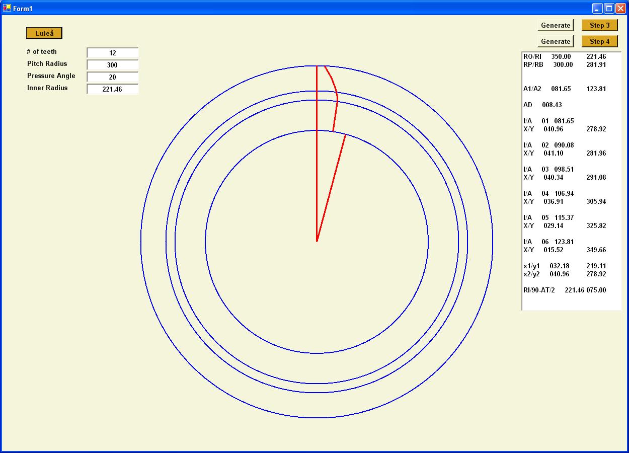
Okay, there's your full tooth. Now I've got to approximate a radial connect on the surfaces on top of the tooth and in the gap between teeth and I've pretty much got it.

Comments:
For gears, don't forget SpiroGraph... using long-loop layup techniques distributes forces along the entire length of the strand, especially if it loops around the central core/spindle or other mounting structure, around bolt holes, and whatnot. hint: use numerical functions rather than metalic style structures when using soft materials, though the gearings will look somewhat strange, the distributed forces across multiple gear faces, especially along the thread axis, provide exponential strengthening and force handling characteristics.

obviously both a concentric and matched gear arrangement can be calibrated to identical numerical values, the spindle allows for significantly more binding force, along with handling planar distortions (compressed on eachother) and allow for 30% more torque transfer than a normal tooth-tooth binding as one would use metalic gears.

so, think spirograph more than anything else, and one should see how the numbers add up to very predictable meshing and stress transfer along a long edge of tube ends (or linear extrusions)..

-Wilfred
Wilfred@Cryogen.com
 
Post a Comment

<< Home

This page is powered by Blogger. Isn't yours?

Subscribe to
Posts [Atom]