Tuesday, May 16, 2006
A gearbox for Godzilla...
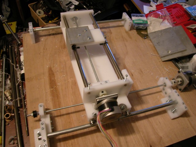
Some weeks ago it became obvious that Vik and Simon were going to get Vik's RepRap going at version 0.1. More importantly, it also became obvious that there was enough internal friction in the Godzilla RepRap as designed to make use of the NEMA 17's to run it at anything resembling a decent speed was pretty far down the track. Indeed, NEMA steppers driving threaded drive rods for horizontal positioning began to appear quite a dicey proposition. That's what I call a learning experience. :-)
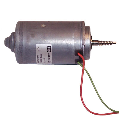
Plainly, if I was going to keep the Godzilla design concept I had to have much more torque available at much higher rotational speeds. Some time ago I had acquired a pair of Siemens gearmotors designed to operate automobile electric windows. Those work on 12v power and have loads of torque.
Yesterday, I drove the Godzilla z-axis with one of them at 12v and today I ran it at 5v. There is no lack of torque. At 12v the Siemens gearmotor gets 56 rpm. That drives the z-axis at just under 1 mm/sec. The Mark II Extruder is designed for 4 mm/sec and I'd like to think that it can be pushed to 20 mm/sec without a major change in design philosophy. The design problem, then, is to leverage the Siemens gearmotor into getting 4 mm/sec and 20 mm/sec if at all possible out of the Siemens.
The obvious way to get that to happen is with a gearbox. Last week, at Simon's prompting, I wrote a script to design proper (involute profile) gears. That done, this week I've set about to design a proper gearbox for the Siemens.
My first design decision was to use a gear train rather than a simple pair of gears. This was more for space considerations than anything. It also conserves material in that going from 56 rpm to just over 1,300 rpm in one stage requires a rather enormous gear and puts some tremendous stress on the gear driving the threaded drive rod for the positioning stage.
I wanted to keep a constant gear ratio throughout the train to reduce complexity. Eventually, I arrived at a ratio of about 2.8:1. Assuming that the Siemens without a gear box can drive the z-axis stage at about 1 mm/sec, the resultant velocities at each stage of the gear train look like this...
Stage 0 - 1 mm/sec (56 rpm)
Stage 1 - 2.83 mm/sec (160 rpm)
Stage 2 - 7.8 mm/sec (440 rpm) {range needed for the Mk II Extruder}
Stage 3 - 22 mm/sec (1,230 rpm) {range needed for the expected terminal performance of the Mk II}
With that in mind after I got the gear design script running I started making some choices about tooth counts for the gear pair. Interestingly, using Adrian's rule of thumb that gear teeth need to be about 3 mm wide at a minimum it is very easy to use the script with that in mind. For example, if you need 24 teeth in a gear making the pitch radius 24 mm gets you a tooth width of just over 3 mm. Pi is a wonderful thing. :-D
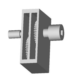
Anyhow, keeping Vik's advice about tooth counts in his tutorial in mind I arrived at a tentative gear pair with 31 teeth in the drive gear and 11 in the receiver. With that in mind I began a design charrette to see how the bits could go together. I decided to make a first shot at two stages so that I could run it at the Mk II's capacity with the option to add another a bit later. Here's what I got on the first cut...
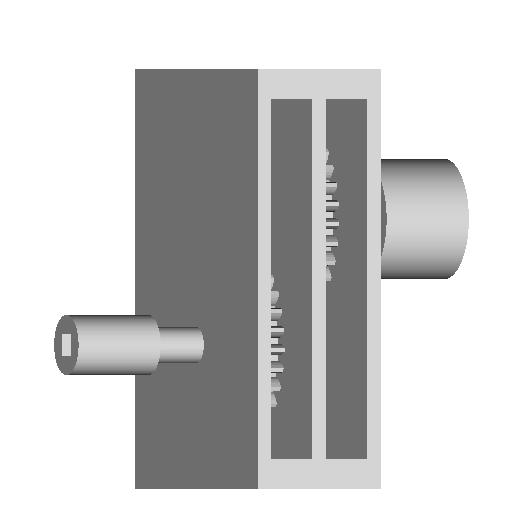
You can see the coupling for the Siemens gear motor on the right and the coupling for the threaded drive rod on the left.
To give you an idea of scale the coupling collar on the right is 40 mm in diameter.
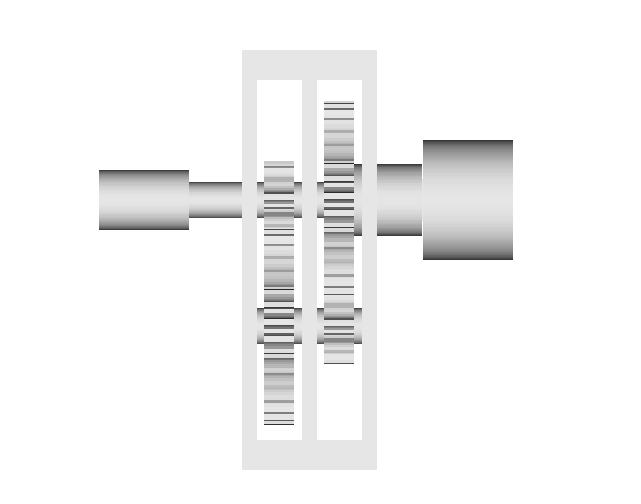
 Tilting the model slightly to the left you can see the coupling collar receives a square drive shaft from the Siemens which measures 14 mm on the diagonal. That works out conveniently to a 9/16ths inch square rod. :-p
Tilting the gearbox slightly to the right you can see a bit more.
I've got to write a script to make a hexagonal profile since the collar connecting to the threaded drive rod needs to work with a long, hexagonal connecting nut. I used a square for now.
My initial feeling was to make the whole thing on the Stratasys. I did some tentative quantity surveys, however, and decided that Adrian wouldn't be glad of that given the volumes required and the cost of filament. Here's a look inside the first stage of the gearbox with the top and connecting collar removed.
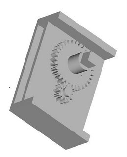
There is a lot of deliberate commonality in the parts for ease of manufacture. Here's a look at the gear train with the housing removed.
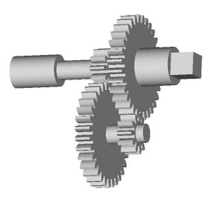
That two stage train gets you 7.8 mm/sec on the positioning stage. Add another stage to that using the same gears and you get 22 mm/sec.
After I got the first cut of the volumetrics of the design done it seemed quite reasonable that I could use standard sheet HDPE to make the housing if I was careful. I was reinspired by seeing one of Sebastien's references where a fellow built a whole CNC machine using plastic sheet.

http://biobug.org/cnc/klunk/
Mind, it would be better, I think, if the whole thing was done out of the same material on the Stratasys given the wayward nature of my drill press. :-s Still, there are other ways to control costs and booking time on the Stratasys if that's a limiting factor. :-)
Looking at the idea in a whole different way I'm sorely tempted to just get a heavy duty DC motor that runs at about 2-3,000 rpm and just step it down by half.

This one from MECI...
http://www.meci.com/product_info.php/products_id/4200577
...draws 2.25 amps and produces 2370 rpm. A simple 1.8:1 gear reduction would produce 20 mm/sec positioning speeds. It costs U$5.95.
An even cheaper and more powerful one by all accounts from MECI...
 ... goes for a ridiculous US$3.95 in one-off quantities.
I'm spoiled for choice here. I feel like the proverbial donkey between two piles of clover hay. :-s
Plainly, if I was going to keep the Godzilla design concept I had to have much more torque available at much higher rotational speeds. Some time ago I had acquired a pair of Siemens gearmotors designed to operate automobile electric windows. Those work on 12v power and have loads of torque.
Yesterday, I drove the Godzilla z-axis with one of them at 12v and today I ran it at 5v. There is no lack of torque. At 12v the Siemens gearmotor gets 56 rpm. That drives the z-axis at just under 1 mm/sec. The Mark II Extruder is designed for 4 mm/sec and I'd like to think that it can be pushed to 20 mm/sec without a major change in design philosophy. The design problem, then, is to leverage the Siemens gearmotor into getting 4 mm/sec and 20 mm/sec if at all possible out of the Siemens.
The obvious way to get that to happen is with a gearbox. Last week, at Simon's prompting, I wrote a script to design proper (involute profile) gears. That done, this week I've set about to design a proper gearbox for the Siemens.
My first design decision was to use a gear train rather than a simple pair of gears. This was more for space considerations than anything. It also conserves material in that going from 56 rpm to just over 1,300 rpm in one stage requires a rather enormous gear and puts some tremendous stress on the gear driving the threaded drive rod for the positioning stage.
I wanted to keep a constant gear ratio throughout the train to reduce complexity. Eventually, I arrived at a ratio of about 2.8:1. Assuming that the Siemens without a gear box can drive the z-axis stage at about 1 mm/sec, the resultant velocities at each stage of the gear train look like this...
Stage 0 - 1 mm/sec (56 rpm)
Stage 1 - 2.83 mm/sec (160 rpm)
Stage 2 - 7.8 mm/sec (440 rpm) {range needed for the Mk II Extruder}
Stage 3 - 22 mm/sec (1,230 rpm) {range needed for the expected terminal performance of the Mk II}
With that in mind after I got the gear design script running I started making some choices about tooth counts for the gear pair. Interestingly, using Adrian's rule of thumb that gear teeth need to be about 3 mm wide at a minimum it is very easy to use the script with that in mind. For example, if you need 24 teeth in a gear making the pitch radius 24 mm gets you a tooth width of just over 3 mm. Pi is a wonderful thing. :-D
Anyhow, keeping Vik's advice about tooth counts in his tutorial in mind I arrived at a tentative gear pair with 31 teeth in the drive gear and 11 in the receiver. With that in mind I began a design charrette to see how the bits could go together. I decided to make a first shot at two stages so that I could run it at the Mk II's capacity with the option to add another a bit later. Here's what I got on the first cut...
You can see the coupling for the Siemens gear motor on the right and the coupling for the threaded drive rod on the left.
To give you an idea of scale the coupling collar on the right is 40 mm in diameter.
 Tilting the model slightly to the left you can see the coupling collar receives a square drive shaft from the Siemens which measures 14 mm on the diagonal. That works out conveniently to a 9/16ths inch square rod. :-p
Tilting the gearbox slightly to the right you can see a bit more.
I've got to write a script to make a hexagonal profile since the collar connecting to the threaded drive rod needs to work with a long, hexagonal connecting nut. I used a square for now.
My initial feeling was to make the whole thing on the Stratasys. I did some tentative quantity surveys, however, and decided that Adrian wouldn't be glad of that given the volumes required and the cost of filament. Here's a look inside the first stage of the gearbox with the top and connecting collar removed.

There is a lot of deliberate commonality in the parts for ease of manufacture. Here's a look at the gear train with the housing removed.

That two stage train gets you 7.8 mm/sec on the positioning stage. Add another stage to that using the same gears and you get 22 mm/sec.
After I got the first cut of the volumetrics of the design done it seemed quite reasonable that I could use standard sheet HDPE to make the housing if I was careful. I was reinspired by seeing one of Sebastien's references where a fellow built a whole CNC machine using plastic sheet.
http://biobug.org/cnc/klunk/
Mind, it would be better, I think, if the whole thing was done out of the same material on the Stratasys given the wayward nature of my drill press. :-s Still, there are other ways to control costs and booking time on the Stratasys if that's a limiting factor. :-)
Looking at the idea in a whole different way I'm sorely tempted to just get a heavy duty DC motor that runs at about 2-3,000 rpm and just step it down by half.

This one from MECI...
http://www.meci.com/product_info.php/products_id/4200577
...draws 2.25 amps and produces 2370 rpm. A simple 1.8:1 gear reduction would produce 20 mm/sec positioning speeds. It costs U$5.95.
An even cheaper and more powerful one by all accounts from MECI...
 ... goes for a ridiculous US$3.95 in one-off quantities.
I'm spoiled for choice here. I feel like the proverbial donkey between two piles of clover hay. :-s
Comments:
<< Home
I'd make the gears a lot wider.
Also, I have umpteen unused, beefy 12V DC motors from Epson tally printers that look a lot like the ones at the bottom there, and a few more scavenged from HP 1315 printers. Free to good homes :)
Vik :v)
Also, I have umpteen unused, beefy 12V DC motors from Epson tally printers that look a lot like the ones at the bottom there, and a few more scavenged from HP 1315 printers. Free to good homes :)
Vik :v)

I'd make the gears a lot wider.
How wide would you suggest?
Free to good homes :)
Have they been grounded? :-s
How wide would you suggest?
Free to good homes :)
Have they been grounded? :-s
Humm... not sure what to say...
Gearboxes are finicky things. How would the rather large amount of backlash be delt with, given several gear pairs, and additionally, plastic parts...
There might also be an issue of flexing plastic gear teeth, getting all of this to stop on a dime (rotational momentum, motor + gears) seems demanding.
Binding might also cause pulses (at several frequencies) in final output/movement of the extruder head or work table.
I'd stick to (bigger?) steppers... sorry for all the doom and gloom, but I like this reprap project you guys are working on!
Gearboxes are finicky things. How would the rather large amount of backlash be delt with, given several gear pairs, and additionally, plastic parts...
...via a directional shaft encoder on the far side of the gear box from the drive motor.
...via a directional shaft encoder on the far side of the gear box from the drive motor.
"...via a directional shaft encoder on the far side of the gear box from the drive motor."
Okay, I was thinking of something similiar, but with a second low res encoder on the motor's shaft. I think it is needed to help deal with the lurch on the first encoder that would occur everytime the motor reverses. I think braking the motor is another issue, but I'm typing way over my head now. You need advice from an expert on these issues, not slobber from an amateur like me! ;)
Post a Comment
Okay, I was thinking of something similiar, but with a second low res encoder on the motor's shaft. I think it is needed to help deal with the lurch on the first encoder that would occur everytime the motor reverses. I think braking the motor is another issue, but I'm typing way over my head now. You need advice from an expert on these issues, not slobber from an amateur like me! ;)
<< Home
![]()