Saturday, April 08, 2006
Still Life With Stepper Controller Board and Stepper Motor....
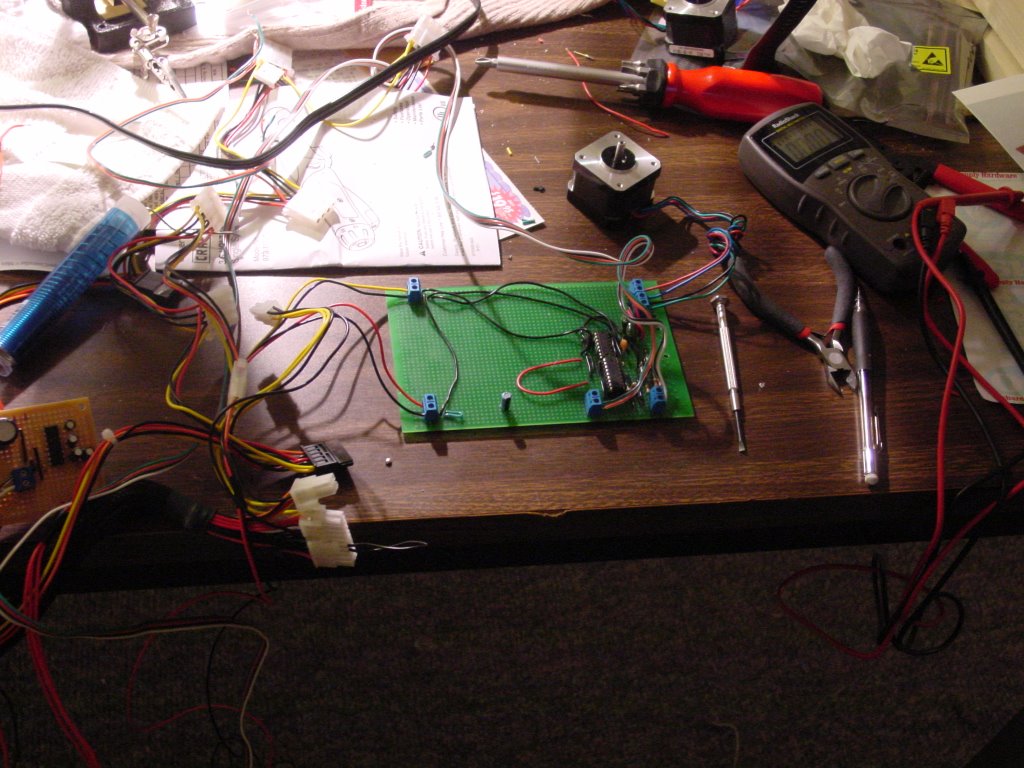 It works now...
After Simon published the debugging protocol in the wiki I decided that I had better regularise my handling of connections to the stepper motor. To that end I installed two screw terminals to handle the connections rather than the direct to motor soldering that I had done earlier.
I was a good boy and walked through Simon's test series for voltages before trying to run a stepper motor. Everything checked out perfectly with ~10.75v being sent to the stepper motor.
Just for luck I hooked up a different NEMA 17 than I had used earlier for the test. That stepper motor turned quite nicely. That SN754410 chip doesn't get half hot! You could cook breakfast on it! :-o
I tested the board for speed and direction and it seemed to respond perfectly.
After satisfying myself that the board worked properly, I swapped stepper motors for the old one. After doing that the whole system froze. It stayed frozen when I disconnected the stepper motor and restarted the exerciser programme. At that point I decided that hot swapping the stepper motors was a bad idea and that I must have fried the board doing that.
I disconnected the stepper board and hot wired the token ring on the comms board and still not even that worked. Hyperterminal wouldn't even echo. It struck me that I couldn't have fried the comms board too so I crawled under my worktable and checked the serial connector and discovered that the pin 3 comms line had broken free.
I resoldered that and resolved to put a housing on the connector in the morning and then went back and checked out both the first and second stepper motors on the comms board after extablishing that both comms board and the stepper board weren't misbehaving in any way.
Both ran nicely.
As hot as that SN754410 chip got I wonder about the sense of stacking them. It also strikes me that on a practical board they need to be spaced out away from the PIC16F628 and from each other and good heat sinks glued to them if we are going to run steppers driving a reprap for long periods of time.
Those are details, though. That's just tweaking, something that I am in a good position to do now that I have a working design. Many thanks go to Simon and Vik for the design and realisation of the bipolar stepper controller board and associated firmware. Well done, guys!
Comments:
<< Home
If the chips get stupidly hot we might have to change drivers - again. Use a fan!
OK, there is another chip we can use but it's getting a bit esoteric at that point.
Vik :v)
OK, there is another chip we can use but it's getting a bit esoteric at that point.
Vik :v)

For me the SN754410 does the job for now. I've got other design issues that I'd like to address instead of continuing to refine a controller board philosophy for bipolar steppers when I'm not even sure that I want to be using bipolar steppers in the next iteration of reprap.
Now that I have a board working I'm going to go buy another eurocard and see if I confect a cleaner layout with all the SN754410's mounted separately. I've got an idea about how to do that that should yield a board that even retards like me can fabricate without a lot of drama.
Now that I have a board working I'm going to go buy another eurocard and see if I confect a cleaner layout with all the SN754410's mounted separately. I've got an idea about how to do that that should yield a board that even retards like me can fabricate without a lot of drama.
Yes, they do get quite hot. Uncomfortable to touch even.
I still haven't mounted a heatsink, and I expect that will help a lot.
Strangely the heat builds up quite quickly as you increase the power but after a while it doesn't seem to get much hotter for further increases. I left one running for about 8 hours on a moderate power level and it was hot but happy.
Actually, I was running two motors for 8 hours. One on a slave board.
The master has a pair of stacked 754410s and the slave had a single one.
They stayed in perfect sync for the full 8 hours, as expected.
The temperature of the single 754410 was about the same as the stack of two.
Post a Comment
The master has a pair of stacked 754410s and the slave had a single one.
They stayed in perfect sync for the full 8 hours, as expected.
The temperature of the single 754410 was about the same as the stack of two.
<< Home
![]()