Tuesday, March 14, 2006
Polygon software

When you slice an STL file with a plane, the result is one (or more) polygons. These have to be filled with RP goo somehow to make a solid in layers. As we are going for FDM, this means offsetting the polygon by half the width of the stream, outlining it with goo, then offsetting again and cross-hatching to fill the interior.
I have been writing Java software to do this. I have decided to do a CSG implementation of polygons as unions, intersections, and differences of planar half spaces (i.e. you treat an infinite straight line as being solid on one side and air on the other so, for example, if you intersect three such you make a triangle).
The reason for this is that, compared to the more obvious solution of storing a linked list of line segments between vertex points, once you've got it working it makes polygons that are guaranteed never to self intersect, are easy to offset correctly, and can themselves be easily combined using boolean operations. The downside is that you have to turn the original slice into a CSG form from what is basically an unstructured bunch of line segments that may join up if you're lucky. Fortunately there's an algorithm for that - Tony Woo's alternating sum of volumes algorithm. Implementing that is my next task.
The picture above shows a test polygon, and the result of offsetting it. If you increase the offset, it all behaves nicely, and automatically avoids lines crossing each other:

Cross-hatching for infill is fairly easy. Here's an inner and outer polygon, both offset, then the result cross-hatched:
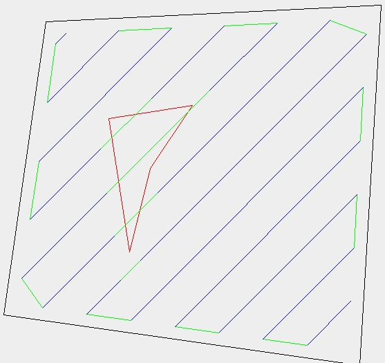
Though I haven't finished that yet - it detects the region in the middle to avoid (different colour), but doesn't link up neatly around it to minimize pen-off-the-paper moves.
How do we do a whole 3D object?
Well, Java3D will read STL files. We slice them from the top down in layers. Imagine that you're at layer N, and the next layer up where you were before is layer N-1. If U is union, - is set difference, PN is the polygon now (at layer N), and PN-1 is the one above, then:
- Get slice PN.
- Fill PN with build material.
- Fill PN-1 - PN with support.
- PN <- PN-1 U PN.
- N <- N + 1.
- If not off the bottom, go to 1.
That defines exactly what needs to happen right the way from the top to the bottom. You work it all out, then play it in reverse from the bottom to the top. This is all particularly simple if U and - are trivial operations, which they are in my implementation. Offsetting is pretty simple too, so things like being able to build slight overhangs without support can easily be accomodated by replacing Step 4. with:
4. PN <- O{(PN-1 U PN), -shrink}
where O{set, distance} is the offset function, and shrink is the width of the overhang that can be sustained.
Job done...
Comments:
<< Home
Your CSG approach reminds me a lot of the methods used in the POV-RAY ray tracing system. If your use of syntax isn't too different, that would mean thousands if not millions of pre-made POVRAY CSG files could be adapted (I restrained myself from qualifying that as "easily") I've got at least a dozen or so I made myself a few years back for some customer's web site images, simulation projects etc. It would be so cool to be able to translate those directly into a matching physical form. It would also mean the converse, you could render some beautifully realistic images in POVRAY prior to actually making the thing. POVRAY is free and supported on most every system out there including Linux so it'd be a good match for those reasons too.

The 3D side is going to be done with Java3D. That'll read STL files and, I suspect, POV-RAY files too. All one will need is a function to cut a plane through a Java3D shape and give back the resulting polygons, either as CSG directly(nice), or as chains of line segments. I'm going to have to handle the latter using Woo's algorithm anyway.
The CSG, incidentally, was all based on the research that John Woodwark (with help from me) did back in the 1980s. He invented almost all the algorithms used in this area.
The CSG, incidentally, was all based on the research that John Woodwark (with help from me) did back in the 1980s. He invented almost all the algorithms used in this area.
Has anybody done any thinking about how to generate the shapes of support structures for parts being prototyped?
I know we could do it by hand, but is there anything out there that could automate the process?
I know we could do it by hand, but is there anything out there that could automate the process?
Another question I've seen mentioned around here but never seen a clear answer to, how do we get from an .aoi or .obj file format to an STL file that your code can eat?
AoI can export STL files; it's a downloadable module.
As to how we get the support sorted; I've added a bit to the page itself as that's:
1. Important, and
2. Actually quite easy...
As to how we get the support sorted; I've added a bit to the page itself as that's:
1. Important, and
2. Actually quite easy...
On a nearly-related note, Google recently bought SketchUp. If you haven't seen it already, watch the demo video on SketchUp's site. It looks like it's ridiculously easy to create models. Not sure what Google's going to do with it but, given their track record, I'd expect a free version to be released at some point.
POVray is something I'm familiar with - I like CSG - and I've got loads of stuff modelled in it for the aerospace industry. The problem is that the scripts are macros, and do not readily import into anything except POVray.
I've used an adapted version of POVray to do space filling, which allows me to create nanoscale shapes filled in by a molecular lattice. Very handy, but not applicable to what we're doing. Not yet, anyway. I'll get around to building the RepRappable STM some day.
Java 3D has one huge advantage over the things Google seem to put out: It's cross-platform.
Vik :v)
Google's stuff doesn't have to be "cross-platform". Anybody with a browser can access the capabilities.
Post a Comment
<< Home
![]()