Friday, February 10, 2006
Building the JDM PIC Programmer Card...
It has been nearly twenty-five years since I built up a circuit board. I wasn't that good at it when I was doing it and the little I knew then I've obviously forgotten. I started out being very businesslike, making up parts lists and buying bits... all well and good.


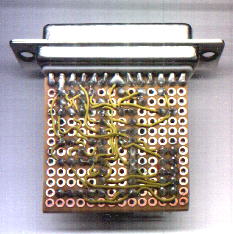
The first thing I remembered that I'd forgotten was how poor my fine motor control (neurological not stepper, mind) is. I remembered that when I started fiddling with the tiny little circuit boards that JDM had bought to put the parts to the board on. The mare's nest of wiring on the back side of the board should have been a tipoff, but no. I was still too green.
Fifteen minutes of trying to wrestle parts onto the 45x45 mm board the JDM used sent me back to the supply shop for something more suitable. I conjured that I could just about work with a 115x160 mm board. Perhaps later I will be able to improve on that, but realistically I doubt it.
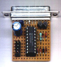
 Next, I sat down and practiced my soldering technique tacking down the 18 pin socket for the 16F628 chip roughly in the middle of the board. I found that I still remembered how to solder, however poorly.
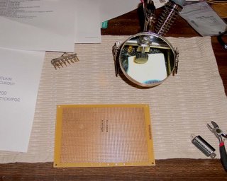
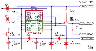
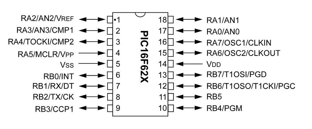
Once finished with that I grabbed a copy of JDM's circuit diagram and started to look at parts to put on the board. Then it hit me, is this circuit diagram looking from the top or bottom of the circuit board? What was the convention? I certainly coundn't remember. The circuit diagram is remarkably unhelpful. No notch mark... no pin 1 note... nothing. That U1 mark at the upper left of the 16F628 might mean pin 1, but it would be nasty to do the whole board and then realise that I had a mirror image of what I actually needed.
Digging around on the Microchip website I found a pic of the chip with the pinouts.
Yup, I was looking at the top of the board. I knew where I was at.
At that point I took the JDM schematic into Photoshop and did a horizontal flip on it so that I could see what the traces would look like from the back of the board.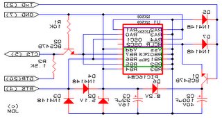
This must all seem rather ridiculous to you circuitry designer pundits on the team, but I am trying to put myself in the position of about a 14 year old tyro that wanted a Reprap to build action figures that he'd captured out of his favourite video game. Things had to be simple and conceptual leaps had to be very short indeed or we were going to lose such people. For a guy in the Third World, things were likely to be much worse than that. I've taken a few notes from the Gingery DIY books, which have some good ideas on presentation. Even those aren't as well thought-out as they need to be.
You circuit designers have probably already figured out where I am going with this. The component layout on the schematic and the component layout on the board are going to have a one-to-one correspondence. I don't think we can depend on our early adopters having the sorts of topological skills in mentally flipping circuit diagrams that a circuitry designer or even a hobbyist with a few years experience has. Even if all the pieces to a Reprap came in a box with subassemblies already put together this device is not going to be a trivial thing to assemble and get going. I feel that we need to be simpler than possible where ever we can. :-)
The first thing I remembered that I'd forgotten was how poor my fine motor control (neurological not stepper, mind) is. I remembered that when I started fiddling with the tiny little circuit boards that JDM had bought to put the parts to the board on. The mare's nest of wiring on the back side of the board should have been a tipoff, but no. I was still too green.
Fifteen minutes of trying to wrestle parts onto the 45x45 mm board the JDM used sent me back to the supply shop for something more suitable. I conjured that I could just about work with a 115x160 mm board. Perhaps later I will be able to improve on that, but realistically I doubt it.
 Next, I sat down and practiced my soldering technique tacking down the 18 pin socket for the 16F628 chip roughly in the middle of the board. I found that I still remembered how to solder, however poorly.
Once finished with that I grabbed a copy of JDM's circuit diagram and started to look at parts to put on the board. Then it hit me, is this circuit diagram looking from the top or bottom of the circuit board? What was the convention? I certainly coundn't remember. The circuit diagram is remarkably unhelpful. No notch mark... no pin 1 note... nothing. That U1 mark at the upper left of the 16F628 might mean pin 1, but it would be nasty to do the whole board and then realise that I had a mirror image of what I actually needed.
Digging around on the Microchip website I found a pic of the chip with the pinouts.
Yup, I was looking at the top of the board. I knew where I was at.
At that point I took the JDM schematic into Photoshop and did a horizontal flip on it so that I could see what the traces would look like from the back of the board.

This must all seem rather ridiculous to you circuitry designer pundits on the team, but I am trying to put myself in the position of about a 14 year old tyro that wanted a Reprap to build action figures that he'd captured out of his favourite video game. Things had to be simple and conceptual leaps had to be very short indeed or we were going to lose such people. For a guy in the Third World, things were likely to be much worse than that. I've taken a few notes from the Gingery DIY books, which have some good ideas on presentation. Even those aren't as well thought-out as they need to be.
You circuit designers have probably already figured out where I am going with this. The component layout on the schematic and the component layout on the board are going to have a one-to-one correspondence. I don't think we can depend on our early adopters having the sorts of topological skills in mentally flipping circuit diagrams that a circuitry designer or even a hobbyist with a few years experience has. Even if all the pieces to a Reprap came in a box with subassemblies already put together this device is not going to be a trivial thing to assemble and get going. I feel that we need to be simpler than possible where ever we can. :-)
Comments:
<< Home
//I don't think we can depend on our early adopters having the sorts of topological skills in mentally flipping circuit diagrams that a circuitry designer or even a hobbyist with a few years experience has.//
I know what you mean. When I draw up schematics for myself, I draw the components in a way that's functionally convenient, rather than as a realistic representation of the component itself. I have no trouble dealing with diagrams where the pins aren't in pinout order, remapping them in my head. I often make the mistake of assuming everyone can do this equally well. Best to keep it simple.
I know what you mean. When I draw up schematics for myself, I draw the components in a way that's functionally convenient, rather than as a realistic representation of the component itself. I have no trouble dealing with diagrams where the pins aren't in pinout order, remapping them in my head. I often make the mistake of assuming everyone can do this equally well. Best to keep it simple.

For the stripboard designs I have put on the wiki, there is no requirement for this sort of mental juggling. There are no wires soldered on the bottom, and there is a reversed diagram for the drilling.
For example, see
http://reprapdoc.voodoo.co.nz/bin/view/Main/BuildingAStripboardStepperController
Perhaps what we should be doing is describing how to build a JDM programmer on stripboard, which is much easier to work with. Then people only need to work with one type of fabrication method too.
For example, see
http://reprapdoc.voodoo.co.nz/bin/view/Main/BuildingAStripboardStepperController
Perhaps what we should be doing is describing how to build a JDM programmer on stripboard, which is much easier to work with. Then people only need to work with one type of fabrication method too.
Great idea! Assuming, of course, that stripboard is universally available. I've been having trouble finding it around here and will probably have to order. :-(
If you decide to go the stripboard route, have a look at this: http://www.geocities.com/stripboarddesigner/
There may be something similar that's open-source.
There may be something similar that's open-source.
Stripboard is common stuff, honest. Just not in America :) stripboard.com are redoing their site, so I can't point you there. Some PCB companies are even making their own to fill the demand! But try:
http://www.pcb-supply.com/item.php?id=944&link_str=&link_catg=&partno=ST3U
http://www.futurlec.com/ProtoBoards.shtml
http://www.diystompboxes.com
http://www.avishowtech.com/mbhp/buy.html
High Street stores like Maplins, DSE and suppliers like RS and Farnell also stock it (Radio Shack and Fry's don't). Newark are the US distributors for Farnell, and you can ask them for the Farnell cataloge.
Some call it veroboard (these guys seem a little expensive though):
http://www.rpelectronics.com/English/Content/Divisions/Div_88_140.asp
Vik :v)
Post a Comment
http://www.pcb-supply.com/item.php?id=944&link_str=&link_catg=&partno=ST3U
http://www.futurlec.com/ProtoBoards.shtml
http://www.diystompboxes.com
http://www.avishowtech.com/mbhp/buy.html
High Street stores like Maplins, DSE and suppliers like RS and Farnell also stock it (Radio Shack and Fry's don't). Newark are the US distributors for Farnell, and you can ask them for the Farnell cataloge.
Some call it veroboard (these guys seem a little expensive though):
http://www.rpelectronics.com/English/Content/Divisions/Div_88_140.asp
Vik :v)
<< Home
![]()