Wednesday, January 04, 2006
What eD's doing
Happy new year Rappers! After narrowly avoiding casualty by strapping sparklers to stunt kites, I'm back in to the self-replicating groove. This post is to let you know what I'm working on.
I'm devloping a mechanical 3D rig, simlar to Vik's. The top tray will be a bog standard carriage assembly: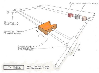 The trick to these things seems to be in the z-axis. Whereas Vik is using studding and a spider to move the z-axis, I'm exploring the possibility of using string. Here's the general concept:
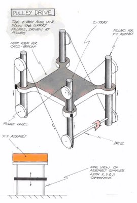
I'm devloping a mechanical 3D rig, simlar to Vik's. The top tray will be a bog standard carriage assembly:
The trick to these things seems to be in the z-axis. Whereas Vik is using studding and a spider to move the z-axis, I'm exploring the possibility of using string. Here's the general concept:I'm currently working on how feasible the idea by building an accuracy test rig. Will keep you posted...
eD
Comments:
<< Home

Has anyone tried using Sarrus' Motion for the Z-axis? Little known predecessor to the Peaucellier (actually a space crank, I think), built of hinged boards that moves two planes normally to each other - I found one in a cupboard of mechanical oddities in the department a few months back, and thought it would be ideal for this job.
Thanks, Ed. This looks like a fairly straightforward evolution from the AoI graphic you posted on May 15.
Do the drawings represent where you are in the design process or have you been generating parts and testing your scheme?
Something I've wondered about is why Vik and you and seem so set on raising and lowering the work surface instead of just raising and lowering the extruder head. Can you tell me about the thinking that led you in that direction?
Just had an interesting idea - if the product is kept still and the head moved over it, could one mount the head on a robot that could crawl over the item in order to position it? That way one could have a machine that could build products arbitarily larger than its own axes....
Tom, have you got a link so that I can see what a Sarrus' Motion looks like? I found a mention of it in Wikipedia under an article about the Peaucellier-Lipkin mechanism, but no drawings.
Try a google image search for "sarrus' linkage"
I fiddled with the one in the lab, and while it looks deceptively "floppy", it's actually solid as a rock.
I fiddled with the one in the lab, and while it looks deceptively "floppy", it's actually solid as a rock.
Just had an interesting idea - if the product is kept still and the head moved over it, could one mount the head on a robot that could crawl over the item in order to position it?
Yeah, you could. The trick is to know exactly where the robot is. It's been something I've been toying with for 30-odd years now and one of the main reasons I'm participating in RepRap now. The team here is thinking about a lot of the problems that I contend with in making that scheme work. It's been a Godsend for me to be around some people who are actually confronting the same problems I'm interested in for a change.
Yeah, you could. The trick is to know exactly where the robot is. It's been something I've been toying with for 30-odd years now and one of the main reasons I'm participating in RepRap now. The team here is thinking about a lot of the problems that I contend with in making that scheme work. It's been a Godsend for me to be around some people who are actually confronting the same problems I'm interested in for a change.
Finally found an illustration under Sarrus mechanism.
http://web.mit.edu/2.72/www/lectures/session_5_v2.pdf
Very straightforward, like most great ideas.
http://web.mit.edu/2.72/www/lectures/session_5_v2.pdf
Very straightforward, like most great ideas.
I think part of the sense behind the fully three-axis platform is so that there is only one vertical motion mechanism, and it doesn't have to handle moving what is potentially the most massive part of the machine. Keeps motor counts down.
I like the string menchanism. Reminds me of the internals of an Etch-A-Sketch. You can have all four corners run off the same string if you zigzag the string around the perimeter of the rig. Instead of 2 Xs, you end up with 4 Ns. This would ensure that the two sides don't slip relative to each other. The main drawback is that you now have strings runnig across all four sides. There might be, with a bit of fiddling, a way to keep one side open.
Nice one, Ed. I think the problem with the vertical axis is going to be making sure that the guides don't bind on the support rods. This was the main reason why I switched to using studding to both support and move the axis.
Sarrus' Mechanism suffers from having 6 precision bearings needed to support the platform, all of which experience loads from variable directions. Can we maintain the accuracy through this?
Cornell have built a very similar device, the SFF. One interesting aspect of it is their use of concrete to construct the supporting structure:
http://www.emeraldinsight.com/Insight/ViewContentServlet?Filename=Published/EmeraldFullTextArticle/Articles/1560100107.html
They've been printing zinc-air batteries and seem to have a source of flexible conductive plastic.
Vik :v)
Sarrus' Motion: A genius contraption. Wish I could have a go with one. Not so hot as a transmission & VIk's point about the bearing's is fair, but its location characteristics (combined with an extra simple linear transmission) make it really interesting.
Drawings: They represent the concept level only. I've made critical pulley parts which are currently under test. Will put up a shot of the rig soon.
Configuration: I've always gone for a static xy table and mobile z tray because of the weight factor. The xy table is looking to be considerably heavy compared to the weight of the z tray (despite the average weight of a built plastic component on it). Moving the heavier weight increases the power consumption, motor capacity, necessary mechanical stability, unwanted vibration, wear & worsens confidence in a blind poisition control system (which mk1 may well be). However, I may be missing out on some crucial advantages which I haven't thought about?
Crawling concept: Having said all that, nothing would be sweeter than watching a legged contraption crawl over the static part it would be building... (memories of the matrix?)
2 X's vs 4 N's: Yes! And the non-slip advantage is very appealing. We can open up a side by simply throwing an extra ider roller into the design.
Tray binding on the runners due to misalignment: My biggest fear. Location manufacturing is one thing that RP cannot do (but it gets pretty close) so this rig will be a real test in adjustable assembly.
Now to check out Cornell...
"We can open up a side by simply throwing an extra ider roller into the design."
Nice! A relatively simple mod and it potentially allows all four sides to be open. You'd probably need to keep one diagonal stretch to allow free movement of the turnbuckle (assuming there is one).
Post a Comment
Nice! A relatively simple mod and it potentially allows all four sides to be open. You'd probably need to keep one diagonal stretch to allow free movement of the turnbuckle (assuming there is one).
<< Home
![]()