Tuesday, September 22, 2026
Square and Hello World, but not like I intended.
Cut to the chase. Have this wondrous bit of psychedelia:

The writing is 250μm across. That's meant to be a 100μm square at the bottom, but obviously I need to work on something. The lines are approximately 10μm thick. I think they're about 50μm high but don't quote me.
How? You may ask. Well Diffraction Limited did this video where they used their very high tech 3D manipulator to 3D print using a 4μm optical fibre and a UV laser. I don't have that stuff. But thanks to a helpful donation to my Ko-fi account (hint), I could get some cheap 9μm fibre and I do have a 1W UV LED. Now you'd normally use some kind of fancy coupler to connect the fibre to the light source. I, uh:

Yah. The other end of the fibre, obviously needs a high precision connection to the μRepRap which..

..kind of degenerated into a couple of zip ties. None the less, if I smeared out a layer of resin, set the movement speed to 1 micron per second, and did about 10 circuits , I could set up 50μm or so of resin in a 100μm diameter cylinder:

So there's my 100 micron minimug. Got to run. Hope you enjoyed.


Saturday, September 19, 2026
Square Tip Test, Blunt Ogive, actual squares, Take 9
Probe #19 was manually etched. I put it in the etchant to a depth of 20mm for 60 seconds. Then, oh so tediously, tapped the tip on the meniscus 80 times. There's dedication. I'll put the picture later because people are bored with pictures of the tips in thumbnails.
So here's a picture of actual test squares. The one on the right is 640μm square, the thing on the left is kind of freehanded. Dot spacing is 40μm.

The interesting illumination in that micrograph comes from me shining a light down the other eyepiece of the binocular microscope. I just happened to notice a lighting change, experimented, and this photo came out pretty good.
Drawing the dotty square shows that Probe #19is having wee issues with flow control. I suspect it was contaminated with superglue during fixing, and the slight unevenness probably isn't helping:

It' slightly asymmetric at the tip. This probe is not etched to a perfect tip and then blunted, it's etched to a vaguely round end and then gradually sharpened. It may be that the sharpening process does not result in a perfect point.
Anyhoo, when I do get a dot, it's about 20μm diameter, which is pretty much what I'm aiming for. The first dot is always larger than all the others which is why, for instance, the top left corner is joined up.
The left square is just me noodling with the probe in direct contact with the slide while being moved around. As you can see, this does not result in a terribly even line width when flow control is poor.
One other "failed" experiment: I tried drawing on a glass slide with thin conductive silver ink CircuitScribe Electon Inks electroninks.com), the idea being to etch a circuit into it in the same way as one mills PCBs. Sadly, the ink did not cover well, and I think that particular ink needs to permeate paper in order to achieve proper drying and a good thickness of conductive medium. Doesn't work well on glass or shiny cardboard anyway. Dries too fast to be deposited by probe.
Friday, September 18, 2026
Small Square Tip test, Take 8
Getting closer. The previous tips were far too finely pointed and were depositing micron or sub-micron dots of resin that I had difficulty positively identifying. This ogive point etch is way too efficient! So I manually took Probe #14 and blunted it a lot by dipping it 30-40 times in the meniscus of the electrolyte etch.
This produced the following tip, which I very enthusiastically drove into the glass slide. I was trying to make absolutely sure I had contact because I could not see the droplets in the USB microscope. I could not get good images on the binocular microscope and had to take the following micrographs of dots with the bench microscope:

The dots are in wavey lines because the tip displaced during my enthusiastic touchdown attempts. The dots appear to be approximately 4μm in diameter. As I want something closer to 10μm or more this tip is still to pointy. Great for etching and very fine detail, but not for building robust microscale tools.
For reference, the resin reservoir only made it up half the smooth part of the point, so about 150μm deep:

I'm going to have to try an even blunter tip. Last time I did this by putting a freshly-cut wire 20mm deep in the etch, which notes say produced a very rough point that had to be smoothed off by a quick dunk on the surface. So that's the next experiment.
Thursday, September 17, 2026
Small Square Tip Preparations, Take 7
I now have a couple of pretty identical tips:

Probe #17 received the second pass treatment (top) with probe #18 for comparison. Might need to tweak the second pass GCODE to take a little more off, but we'll see which one works best first.
I've fitted Probe #18 to a flexure tip holder, and Probe #17 to a holder that has been extended so that I can get the microscope angled more vertically over the probe:

I'll try that one when the glue has set and I've put the Z Axis back on the PIKA.
Monday, September 14, 2026
Small Square Tip Preparation, Take 6
I wanted to get the tip right, and the tips I was making just weren't ogival enough. For those going "Wut?" an ogive is the shape of a pointed gothic arch. I made another probe tip because I wasn't sure how this would play out. After the automated two-pass etching process (without roughening) it looked like this:

It's too aggressive. It needs to be less pointy.
It might be fine for depositing teeny little dots, but what we're trying to do is lay down 20μm-30μm lines and build something relatively solid. The catch is that we need to do that without flooding the nascent part with a torrent of resin. The ogival point I created for Probe 10 seemed to do that well.
I ran the second half of the automated etching GCODE that basically tried to etch off the last 2μm at a time. I noticed that it etched off roughly 8μm at each dip, so a lot of dipping time was wasted. I wrote a second piece of GCODE that dipped 5μm at a time and ran that. I took off approximately 110μm of the point and it looked like:

Now this is much more like the desired ogival outline, and the area above the tip is roughened so it should hang on to a layer of resin by capillary action. I'll mount this one in a contact flexure and we'll try it out. [Edit: Turns out I put my monitor on top of the last printed flexure so will have to print another]
Thursday, September 10, 2026
Small Square Findings Etched Tips, Take 5
The blog has stopped accepting images for unknown reasons (bug-a-minute here), so this one is pointing to my Mastodon account on the NZOSS server. I hope it works. If it vanishes, sorry, I have the original.
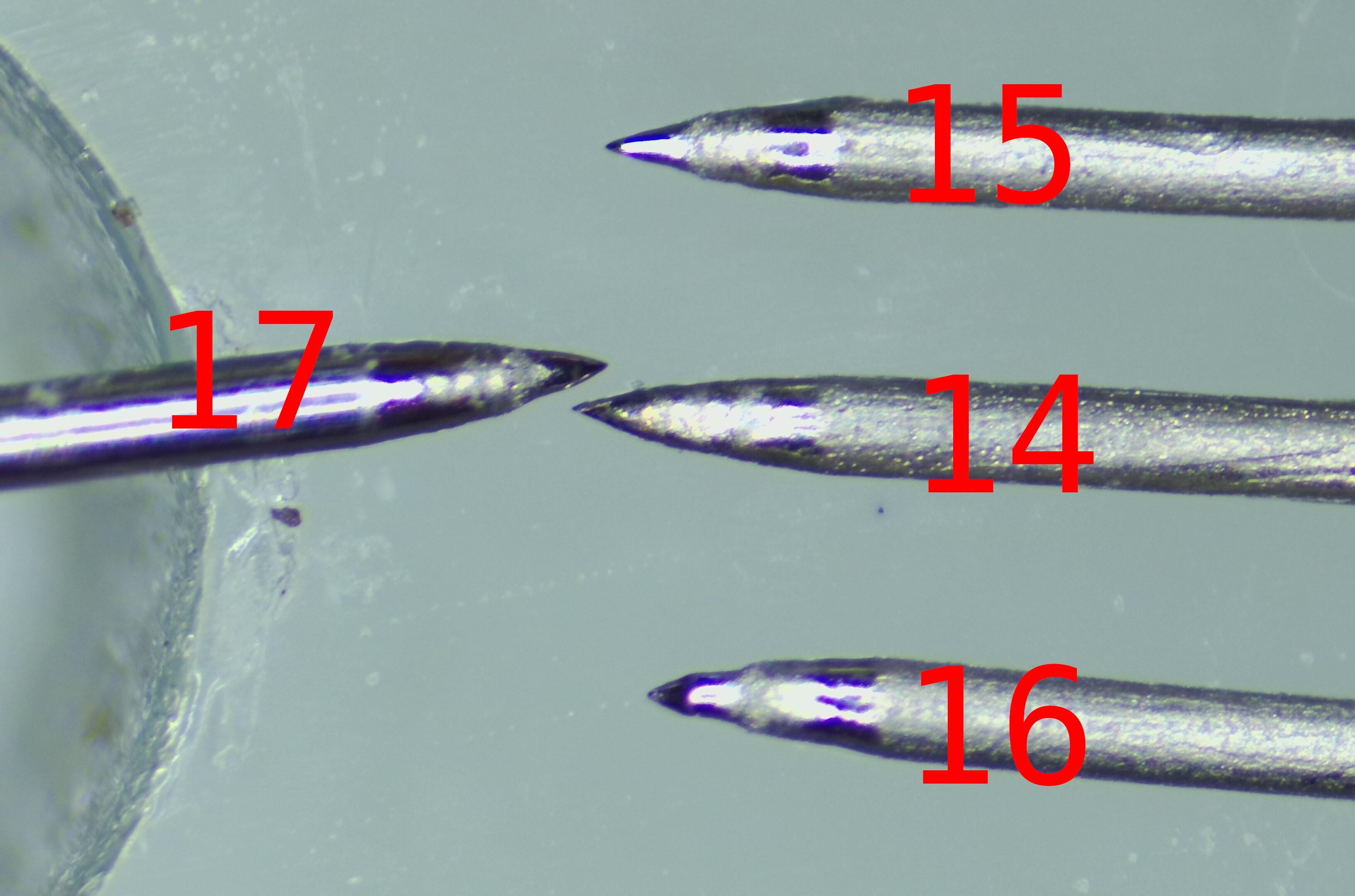
What you should see here is four etched probe tips, numbered, etched from 0.3mm 316L SS wire. #14 was made a couple of days ago before my Z Axis died. That was given a 20 second roughening etch, then the GCODE-controlled etch as per the github repo /utils directory. It has a smooth ogival point.
#15 and #16 were the ones that ended up malformed due to the misbehaving Z Axis. I cut the tips off, and re-etched the wires using the same GCODE as #14. These display a significant stepped profile to the point. Not what I was looking for.
So I wondered. What effect is the roughening etch having on the point profile? So I etched #17 with the same GCODE as #14 but did not do a roughening etch on it. The ogival profile is very good.
All of the probes display a slightly roughened area about 0.1mm behind the tip. This is unplanned but fortuitous. I will experiment with #17 to see if the roughening process is worthwhile when using the sodium chloride etch. The nitric acid roughening etch certainly soaks up the resin, but I have not seen any of this behaviour on the sodium chloride etched tips unless they are over-dipped. Over-dipping is not good for accurate resin deposition as it results in a roughly spherical blob held on the tip by surface tension rather than a film held by capillary action.
Anyhoo, now have tips. Next step is to mount them to the Flexured Probe Holder I printed earlier.
Tuesday, September 08, 2026
Small Square Findings and more breakage, Take 4
I took the Z axis off and followed my own instructions https://github.com/VikOlliver/RepRapMicron/wiki/Probe-Tip-Fabrication-And-Assembly to build three probes. When I started doing the second one, it was pretty obvious something was wrong because I had to raise it much higher above the etchant to break it clear of the meniscus. They came out like this:

Hmm, maybe one is usable but it looks a bit too sharp. After poking around at the Z axis I determined that the locknut at the top of the ZAxis Drive Screw was no longer in the right place. It seemed tight enough. It's possible it released and then re-tightened itself. It's also possible that the Flexure Coupling on the stepper motor has failed or compressed, or that I never had it right to begin with and just got lucky.
Anyway, it is re-tightened. I'll just chop the ends off and try again tomorrow.
I am still not capable of putting more than a couple of hours at a stretch in at the bench I'm afraid. The Doc is pleased with my progress, has upped the painkillers slightly, and - within sensible limits - is allowing me to drive again. So there's improvement somewhere anyway!
Oh, if anyone can donate me any single mode fibre cable, OS1 or OS2 or anything with a 9/125 fibre core or finer, would be appreciated. Why? Well, check out this video of someone else's micro-fabricator: https://youtu.be/UvV2CH5il3Q which is using a fibre to spot-cure resin. Not the approach I wanted to take, but they get more views than me so I have to get with the program and be relevant :) The same arrangement will work just fine on the RepRapMicron.
Monday, September 07, 2026
Probe Flexures With 0.1mm Layer Build
I printed the Probe Flexure with a 0.1mm layer height on the Prusa XL and they came out really nicely. Worth doing in the future.

Still haven't etched the new probe. Thought I'd make a proper set of croc leads with a plug on, got croc clips, Du Pont connectors etc. and then cleverly put a socket on the leads instead of a plug. Arrgh!
Sunday, September 06, 2026
Small Square Findings and wreckage, Take 3
I believe the USB microscope was resetting and misbehaving because everything was plugged into a USB 2.0 hub. I don;t think it could handle two high-res cameras with lights and an Arduino. Something gave. So I have replaced it with a USB 3.0 hub (any donations for my rapidly shrinking personal hardware fund to https://ko-fi.com/viksworkshop ...) and it seems to stay up for 5 mins without flashing the red light at me.
However, as is the way of things at the moment, I broke the flexure probe when fitting the microscope back on and not paying attention:

And so I have to make another one. I'll have to make a new tip as well because I really smacked the point into the slide hard and blunted it:

So that's another hold-up. 'Tis the season, apparently.
Wednesday, September 02, 2026
Small Square, Take 2 ...
This time I'm making the very thing smear on the slide before I put it in the μRepRap. For reasons unknown, the microscope then crashed and flashed it's little LED at me. Reset everything, try again. Problem repeats. Unplug everything, reset everything, try again. Damn.
Okay, microscope is not playing today and prefers to flash status LEDs instead. I'll clean the slide with isopropyl alcohol and an air blast, put the microscope on charge to see if that helps, and try again tomorrow.
Sunday, August 30, 2026
Recovering and Prepping a RepRapMicron Side
As the last attempt went poorly, I thought I'd take the opportunity to describe how I recover the slide. If you're using a new slide, the preparation is the same but without the initial peeling/scraping.
Required materials: Isopropyl alcohol or (acetone, MEK etc.), wipes (ideally lint-free), boxcutter, tweezers, air duster, adhesive aluminium tape, pointed probe, aluminium foil.

First, scrape up a corner of the old aluminium tape and use tweezers to pull it off together with the hardened UV resin on it.

Then scrape the failed UV resin print off very thoroughly with a fresh boxcutter blade. Don't gouge in the point or use a nicked blade or you'll scratch the slide. Keep the edge flat.
Clean both sides of the slide with solvent and a wipe. Blow dry with air duster or clean shop air.

Cut a square of adhesive aluminium tape, and stick it to one end of the slide. Burnish it down flat with a dry wipe. Pay particular attention to the edge closest to the centre of the slide. Wipe with solvent to remove fingerprints.

Run the tip of a pointed probe along the edge of the tape. Push into the join, but not so firmly as to scratch the glass. The objective is to cause the edge of the tape to curl up slightly and present a barrier to UV resin that might otherwise encroach on the slide.

It's hard to catch it in the focal plane of the microscope, but you might be able to make out the raised edge above. It doesn't have to be particularly tidy, it's just a barrier.

The slide is then rinsed with solvent, dried with an air blast, and wrapped in aluminium foil until needed.
Well, that's how I do it at the moment.
Friday, August 28, 2026
First Square Attempt. Goal - Perfecting the method
This didn't go to plan, but the failure was instructive. I started with drawing a 16x16 hollow square (black pixels on white background) then using this to create the GCODE:
../png_to_gcode.py 16x16_hollow_square.png -d 10 --safe-z 30 --dipify 100 -o test.gcode
The "dipify" tells the code to dip the point in the resin initially and every 100 points. That function does not currently do a UV exposure, so I'll have to remember to do that for now.


A little bit of Kapton tape folded flat over the end of a stick is used to push the droplet into a smear. This was my first mistake. I should have pulled the droplet away from the edge after pushing it forward. I've been away from this too long...


If you zoom in on the probe point here, you'll see the problem. The surface tension high up the point has caused a relatively large droplet to form, dangling from the point. This will make a large blob on contact, not a fine dot.And everything after that point was a mess. So, I set the resin with UV to look at the mess (nothing of note), and cleaned the probe with IPA. I'll scrape the slide clean with a box cutter blade, then IPA, then a blast of compressed air, and remake the slide for another go. Hopefully tomorrow as I'm working today.
Wednesday, August 26, 2026
Stacking Squares Without Slicer on RepRapMicron - The Experimental Plan
Soooo, turns out I needed quite a lot more of the blocker pills once I got up and about, and something else cropped up during a scan. Damn. I think I'm back on top of it though. Can walk with stick, even allowed to drive the 10 mins to town (but no further). So back at the workbench, which currently looks like this:

I'm having too may problems with artefacts from slicers when trying to deposit objects. Anyone want to help write a custom slicer?
[crickets]
In that case, to make progress, I'm going to use the png_to_gcode.py script to make something simple and repeatable, where I can alter one variable at a time. That script takes a black and white pixel image and plots it as dots of resin with a spacing and height of the user's choice. So far I've only really used it for etching in Sharpie marker.
The plan:
Determine voxel spacing needed to deposit a square that clearly isn't blobbing in at the corners. How many microns between points? Is one row of points enough for a reliable line?
Establish the height of the square's sides.
Deposit a second layer. Determine the height of that.
Repeat, third layer.
Now this all sounds nice and straightforward, but I'll be really lucky to get this done with three resets or less. I have to clean/swap probes before measuring the height of something for a start.
How far have I got? Well, I have moved the RepRapMicron onto a sturdy bench that is separate from my keyboard, so that I can operate the machine without vibrating things. I've shortened the microscope pole to lower vibrations off that, and I've prepped a slide with an aluminium reservoir (I'm using adhesive aluminium tape). I have a 16x16 PNG of a square to start with.
But I have to meet a good friend in an hour, so I can't start now. Hasta Mañana, Amigos.
Wednesday, August 19, 2026
The Sub-Millimeter Challenges
The FPath Project is an R+D effort to follow the Feynman Path to Nanotechnology - the use of tools to build smaller tools which then build smaller tools and so on. The ideal situation would be the eventual development of kits of tools and techniques applicable to various scales (sub-millimeter, micron etc).
In order to bias the direction of the FPath Project experiments towards this goal, a series of challenges has now been created - each of which solves a useful problem.
http://www.ofitselfso.com/FPath/SubMillimeterChallenges.php
The FPath Project will attempt to complete each of these challenges - but they are generally open to others. If you complete a challenge (or even make a valiant attempt) I am happy to post a link to your solution on the the Results Page.
New Challenges will be added in the future and suggestions are appreciated.
Labels: Additive Manufacturing, Feynman Path, Nanotechnology
Tuesday, August 18, 2026
Under The Binocular Microscope
I can now sit at the desk again for a bit, and slide things around the bench. Tremor from blocker pills is fading, and I can manipulate tiny things. So I've shuffled the μRepRap under the binocular microscope:

This gives me an enormously better view. Erm, 3 wee issues:
1. While binocular vision is very nice, I can't share it on the blog.
2. When looking into the binocular microscope, I can't operate the CNC jog controls.
3. I can't bend over to look through the eyepieces for very long right now.
4. It does rather get in the way, doesn't it?
I'm collecting ideas for when I'm declared fit again:
Cheat like hell to get a useful micron-sized tool.
Etch a pattern into some Sharpie or other masking material, then drop resin on top, then expose the resin through the etched Sharpie mask.
Try the old "write on a grain of rice" trick.
Nail some CNC joystick control software that allows constant acceleration with an analogue stick.
Wednesday, July 22, 2026
Protection For Touch Probe Tips
When removing the previous probe, the one with the touch indicator on it, I realised I didn't have anywhere to put it! So, I've uploaded a newer version that has a tip cover that can be attached using a screw.

I'm going to have to construct some kind of enclosure for the μRepRap, as I'm having problems with sunlight prematurely curing the resin during a print. The tip on the probe in the picture above is in fact caked solid.
Progress too on the RepRapMicron mailing list software, "listomail", which now supports the redistribution of file attachments to the mailing list. I've yet to add autoreply detection, and the IMAP handling relies on tickling the IMAP timeout with NOOPs too much, but I think the list server script is now sufficiently reliable for regular use. So pipe up if you want to join the email list.
Friday, July 17, 2026
Using Raking Light To View Resin Droplets
Fired up the μRepRap after nigh on a month, and after damp weather following an air conditioning failure. Still in good alignment, so I had a go at a resin print.
As expected, the steeper angle on the probe used produced a bigger droplet size (hey, it was what I had fitted at the time). This may seem counter-intuitive, but I've seen this before and I suspect that a thicker probe tip pulls more resin back due to capillary action. The deposited first layer was approximately 8-10μm thick. Here's a shot of me doing a few tests of micromugs:

The takeaways from that run are:
Raking light from the top camera (now angled in at 45 degrees or so) is causing reflections at the contact point between the resin and the slide. This was a suggestion from a fellow Fab Labber. This, together with the 4K microscope, allows coated probe contact to be visualised relatively easily compared to previous efforts.
The first layer appears to be substantially thicker than subsequent layers. This is a slight problem, because current slicers all let you set the thickness of the first layer by determining the standoff distance to the bed for the first layer, and with μRepRap, the layer always starts at zero. Prusaslicer does seem to have individually configurable layer heights though, so I'll have to play with that.
Eventually this is going to need custom software, but I currently don't have the resources to manage that and I'll have to fake it.
PS I'm feeling fine now, but have to go back in hospital in a week to be introduced to some tiny little cameras so they can figure out WTF is going on. I hope they're narrower in diameter than my microscopes!
Monday, June 29, 2026
Update on mailing list and human factor
Last few days have been interesting. RepRapMicron mailing list attempts resulted in my SMTP IP being blocked by Google because I had the temerity to send out 20 emails at once. I'll add in rate limiting. I've put the code on github https://github.com/VikOlliver/listomail in case anyone who knows anything about writing mailing lists wants a laugh.
My time has, however, been limited for medical reasons which have left me a tad fuzzy-headed. These got even more fun when combined with floods that've cut off a lot of the local area (including the hospital) and me suddenly finding out that I'm quite allergic to a prescribed antibiotic while on the other side of said floodwater. Can breathe easily again and improving.
Tuesday, June 23, 2026
RepRapMicron Mailing List Update

A couple of days ago the server running the RepRapMicron mail chat server (NOT reprap.org) was turned off permanently. This left me in a bit of a pickle because I run a few mail chat lists. I *thought* I'd just run up the mlmmj Open Source software like in the good old days, but it turns out that me and mlmmj no longer get along. So I have been forced to write one that runs with very limited resources.
"listomail" can vet incoming messages for redistribution now, but the retry-on-fail stuff doesn't work yet, thus the bit that deletes the incoming message when it has been sent doesn't work either. However, I'm getting there.
Sorry about the diversion from hacking physical hardware, folks. Admin stuff needs doing, I need a bit of a break to do it, and other projects are also on the line here.
Your friendly BOFH
Wednesday, June 17, 2026
Touch Probe Documentation Online
I'm being distracted by doctors again, but have managed to document the latest incarnation of the Touch Probe on Github https://github.com/VikOlliver/RepRapMicron/wiki/Touch-Probe and put the STL file on Printables https://www.printables.com/model/1755519. Enjoy.

