Thursday, November 30, 2006
Universal PCB test
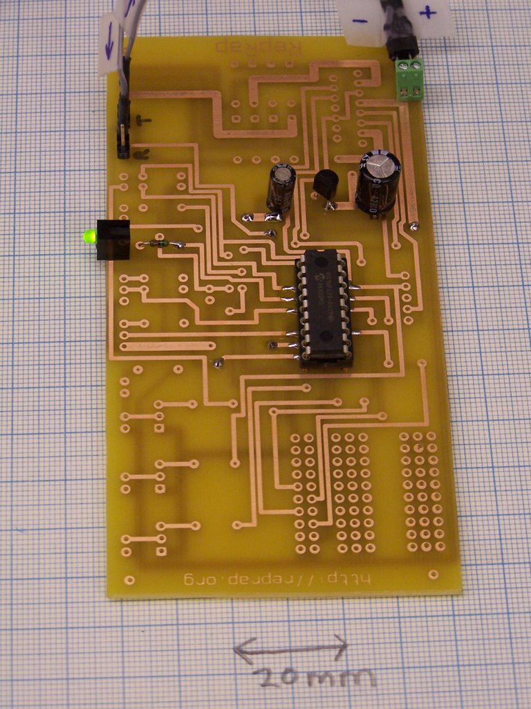
Here is the first test of the universal PCB:
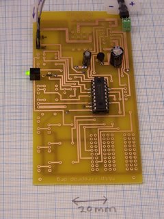
As you can see, it is not fully populated. We are trying to design RepRap so that not only can you test parts when they're finished, but so you can also test them as they're being built too.
Here I have just added the smoothing caps, the 5V reg, the PIC chip holder and the what-the-hell's-going-on? LED.
Pouring 12V into it made the LED light up, as you can see.
Better was that, when I programmed the PIC with Simon's stepper firmware then put the board in the token ring I could make the LED flash by running the RepRap Java software and asking it to move the X axis. The LEDs are supposed to flash when the motors turn, so all seems well. Now for the stepper-driver H-bridge chip...
Incidentally, the busy area bottom right is a breadboard area in which users can build their own circuitry (Vik's idea).
Comments:
<< Home

That's the general idea. Plus a comms board.
The good news is that this is only going to be needed for 1.0, as later versions will produce their own circuits.
Remember that we want to eventually eliminate any need to use a soldering iron.
PS She's looking good, Adrian!
Vik :v)
The good news is that this is only going to be needed for 1.0, as later versions will produce their own circuits.
Remember that we want to eventually eliminate any need to use a soldering iron.
PS She's looking good, Adrian!
Vik :v)
This is really getting me excited about doing a single board controller for Tommelise.
***Remember that we want to eventually eliminate any need to use a soldering iron.***
You might be able to get by without a soldering iron with Tommelise, though I doubt it. There's no way you're going to be able to build a controller with an L298N in it without solder, though.
***Remember that we want to eventually eliminate any need to use a soldering iron.***
You might be able to get by without a soldering iron with Tommelise, though I doubt it. There's no way you're going to be able to build a controller with an L298N in it without solder, though.
Adrian, I totally love this idea. Much cleverness. Will reach out to a lot of people who are not very confident on the electronics side.
Vik found a competition for "PCB of the Month" the other day, in which the winner gets their PCB fully made up with through-plating, silk-screens etc. When we get this all working we could enter it, then (if we win...) reprappers everywhere could just order the PCBs from the competition site (I think).
I want to do one for the comms board and little ones for the optoswitches for the axis endstops as well. Then we'll do one big board with perforations so it can be broken up for all 5 controllers, 6 optoswitches and one comms board. This is the tricky one - the comms and optos should be very easy in comparison.
I want to do one for the comms board and little ones for the optoswitches for the axis endstops as well. Then we'll do one big board with perforations so it can be broken up for all 5 controllers, 6 optoswitches and one comms board. This is the tricky one - the comms and optos should be very easy in comparison.
Forrest, I'm sure we'll get along with L298N's and no soldering, even if we have to stuff them into wire-wrap sockets to get them far enough away from the melting stuff!
Then there's the "nuclear option" - pick something that runs a darned sight cooler. By the time Mendel comes along, we'll be running on DC servos anyway.
Vik :v)
Then there's the "nuclear option" - pick something that runs a darned sight cooler. By the time Mendel comes along, we'll be running on DC servos anyway.
Vik :v)
Well, I'm going for the nuclear, then, I guess.
My suspicion is that you could ship several dozen of the PCB boards to one of the little robotics hobby firms and they'd offer them either with a sack of components with them or assembled for a higher price. That would get us away from the people who would take fright at the notion of picking up a soldering iron or debugging a board they'd built up.
My suspicion is that you could ship several dozen of the PCB boards to one of the little robotics hobby firms and they'd offer them either with a sack of components with them or assembled for a higher price. That would get us away from the people who would take fright at the notion of picking up a soldering iron or debugging a board they'd built up.
Neat board.
Just out of curiosity, isn't there be a way to use a tiny router bit to carve the PCB, assuming one already has a relatively working repstrap with dremel attachment?
Just out of curiosity, isn't there be a way to use a tiny router bit to carve the PCB, assuming one already has a relatively working repstrap with dremel attachment?
***Just out of curiosity, isn't there be a way to use a tiny router bit to carve the PCB, assuming one already has a relatively working repstrap with dremel attachment?***
I've read of several people who made small positioning systems rather like ours with the notion of doing just that with them.
I've read of several people who made small positioning systems rather like ours with the notion of doing just that with them.
The Reprappers had an alternative idea: put a (bunch of) electrode(s) in a RepRap head and use electrochemical machining to make the PCB. Best electrolyte, according to my colleague Tony Mileham who's a world authority, would be sodium chlorate. Bit dodgy as it's
1. Horribly Poisonous, and
2. A fierce oxidsing agent...
1. Horribly Poisonous, and
2. A fierce oxidsing agent...
Any chance a single-sided universal PCB could be made, with wire links for tracks that cross each other? I've found double sided boards to be a nightmare to make using average hobbyist equipment - it's just incredibly difficult to get the two sides lined up accurately.
I'm,er, familiar with sodium chlorate. I've been accidentally poisoned by it and to be honest it wasn't a big deal. I wasn't even really sick after accidentally consuming a teaspoonful or so of the stuff. Wouldn't recommend it though, even if the LD50 is a few hundred grams (1200mg/kg in rabbits,apparently).
I must say, it's very easy to produce though. Fire 12V into salty water through a couple of old carbon battery rods and there she is.
The proximity of clorates and finely divided long-chain ketones would be a problem, however.
Vik :v)
I must say, it's very easy to produce though. Fire 12V into salty water through a couple of old carbon battery rods and there she is.
The proximity of clorates and finely divided long-chain ketones would be a problem, however.
Vik :v)
***it's just incredibly difficult to get the two sides lined up accurately***
Smug person says: I have no trouble. I print them on overhead projector acetate sheets in a laserprinter (inkjets aren't dense enough) so that the toner side will be the side touching the PCB. I put both on a white sheet of paper, line them up by eye, and stick the sheets together with sticky tape. Then I put the raw board with photoresist between the sheets (it needs to be about a 10 mm bigger rectangle than the finished board) and tape that to the bottom sheet. I do this last bit under a darkroom red-light, because I'm superstitious.
Then I put it under an old sun-tan lamp with a sheet of glass to hold the acetate down for 5 minutes, turn it over and do the other side for five minutes, then drop the PCB in the developer.
Seems to work.
***L298N's still make me nervous. Low power and readily available, but no intelligence.***
But the PIC has. The biggest pain with them is that they don't have the diodes in, which implies a bit of design incompetence at Thompson CSF (or whoever first made 'em).
***Might want to look at something even cheaper/more efficient as a PCB etchant.***
The good thing about FeCl3 is that it is a salt, and so doesn't have an exciting pH. Plus if you warm it to about 60 or 70 C and stir it while it's working it etches fast as a chainsaw.
Bad thing is it stains indellibly - labcoat recommended...
***Is the .sch file for this available? I can tweak it to a white-wired single side and resubmit it.***
Say no more! I'v put a tarball at:
universal circuit as a tarball
Thanks!
***How do you do the through-holes?***
Just solder a bit of wire through them chopped from one of the resistors needed in the circuit. For component legs I just solder both sides if both are going somewhere.
Just solder a bit of wire through them chopped from one of the resistors needed in the circuit. For component legs I just solder both sides if both are going somewhere.
RCM is possible for electronics circuits I have done it . First you have to mask the board then mill it .the common problem is perfect masking solution is not available
Sujith
India
Post a Comment
Sujith
India
<< Home
![]()