Monday, September 28, 2026
UV Thin Film Setting Analysis
I took a few measurements off the micrographs of the most recent "Hello World" and got some data points. First, if I spread a thin film of Nail Art resin as thin as I can without leaving any wrinkles in the surface, the film is about 50μm thick. Any thinner and it starts to glob. I can spread such a film over at least 2mm x 3mm.
Shining UV from the 125/9 fibre a few microns above the film surface causes the resin to cure in the following pattern:

I am advancing the UV fibre along the surface at 2μm/sec. This gives some idea about how simple, flat structures such as folding frames may be designed. Obviously not very high resolution, but I suspect would be a fair bit faster than building something from single layers.
Unfortunately I am dragged away from the workshop once more and cannot conduct further tests on building layers with the fibre probe immersed in resin. My current theory is that it might be best to make the first layer several microns thick, which would effectively level the first layer. Then subsequent layers can be made a couple of microns or less thick.


Thursday, September 24, 2026
Repeat of "Hello, World" with UV fibre fabrication and animation
I've got a process sorted for making thick 2D objects like Hello, World and possibly some structural items. I recreated the HW by the following process:
Text is created from an SVG and converted with jscut.org using a speed of 1000mm/min, 10mm tool diameter, outside cut, cutting 1mm in 10 passes. This effectively goes over the text 10 times while only moving the tool head a micron. I do not claim these settings to be optimal but they are repeatable.
Stick a very small piece of tape on the opposite side of the slide. This denotes where your part will be and makes it a helluva lot easier to find!
On the "right" side of the slide, smear a very small quantity of Nail Art resin (not doing well with 3DP resin yet) and use a manual probe to make sure it covers the taped area smoothly with no bubbles.
Set the μRepRap up, position the fibre as close as you can get to the thin film. Load "Hello World" GCODE. Hit 'Run" and turn the UV on. Wait until it finishes and immediately flip the UV off. In this example I did not flip it off, but moved the tool to (0,0) and then rapidly to (-50,50) before turning the laser off just to see what happened.
The result:

Looking from the side you can get an idea of the thickness. It is interesting to note what happened with the manual move of the UV beam (tail, bottom left). Apologies for lousy photography:

The result is table, can detach from the slide, and appears to be moderately flexible as per this animation. Do bear in mind that when I poke it with a needle it's the equivalent of poking a macro-sized object with an aircraft carrier:

Obviously, this affects plans for making small tools and mechanisms...
Tuesday, September 22, 2026
RepRapMicron Benchy!
Oh yes. Barely recognisable, resting on the sea bed at nearly 3 kilometres down...

Well, maybe not, but if you squint it looks like a Benchy sure enough. The wee beast was sliced on PrusaSlicer, and the GCODE slightly filtered to to 650μm long (1/100th scale) without extrusion and other GCODE commands that confuse the heck out of GRBL.
[UPDATE: See how it comes out after a bit of tweaking http://blog.reprap.org/2026/10/reprapmicron-success-decent-500m-12mm.html]
Next step was to load it all into CNCjs and fire up a couple of microscope views. Then the end of the 125/9 fibre was touched off on the glass slide just by eye, and raised I think 30μm:

Then a drop of nail art resin was deliberately dropped onto the fibre tip. The GCODE was run and the UV source manually turned on. The model tool 13hrs to print with 2μm slicing and 10μm/sec print speed. As non-printing movement speed was far, far higher, it was not necessary to switch off the UV source.
So controlling the UV with GRBL is probably a good idea - I missed the end of the print by 5 mins and kinda irradiated it a bit. Also the UV blasts through already printed parts and sets all the resin underneath. Diffraction Limited uses turmeric extract to fix that. I might do that, or use a UV-resistant marker pen ink.
I think the speed can be cranked up, and the layers made a little thicker. This'll speed the print. Ultimately and improved UV source and greater speed will help.
But overall the process is quite fast, quite easy to set up, and will allow me to print some serious parts even without the above modifications.
I'll talk about the philosophy of moving to fibre/UV another time, it's kinda deep. I'll leave you with a picture of Benchy in progress. It's not easy, but you can just see bits of it inside the resin droplet just under the centre of the white fibre sheath.

Square and Hello World, but not like I intended.
Cut to the chase. Have this wondrous bit of psychedelia:

The writing is 250μm across. That's meant to be a 100μm square at the bottom, but obviously I need to work on something. The lines are approximately 10μm thick. I think they're about 50μm high but don't quote me.
How? You may ask. Well Diffraction Limited did this video where they used their very high tech 3D manipulator to 3D print using a 4μm optical fibre and a UV laser. I don't have that stuff. But thanks to a helpful donation to my Ko-fi account (hint), I could get some cheap 9μm fibre and I do have a 1W UV LED. Now you'd normally use some kind of fancy coupler to connect the fibre to the light source. I, uh:

Yah. The other end of the fibre, obviously needs a high precision connection to the μRepRap which..

..kind of degenerated into a couple of zip ties. None the less, if I smeared out a layer of resin, set the movement speed to 1 micron per second, and did about 10 circuits , I could set up 50μm or so of resin in a 100μm diameter cylinder:

So there's my 100 micron minimug. Got to run. Hope you enjoyed.
Saturday, September 19, 2026
Square Tip Test, Blunt Ogive, actual squares, Take 9
Probe #19 was manually etched. I put it in the etchant to a depth of 20mm for 60 seconds. Then, oh so tediously, tapped the tip on the meniscus 80 times. There's dedication. I'll put the picture later because people are bored with pictures of the tips in thumbnails.
So here's a picture of actual test squares. The one on the right is 640μm square, the thing on the left is kind of freehanded. Dot spacing is 40μm.

The interesting illumination in that micrograph comes from me shining a light down the other eyepiece of the binocular microscope. I just happened to notice a lighting change, experimented, and this photo came out pretty good.
Drawing the dotty square shows that Probe #19is having wee issues with flow control. I suspect it was contaminated with superglue during fixing, and the slight unevenness probably isn't helping:

It' slightly asymmetric at the tip. This probe is not etched to a perfect tip and then blunted, it's etched to a vaguely round end and then gradually sharpened. It may be that the sharpening process does not result in a perfect point.
Anyhoo, when I do get a dot, it's about 20μm diameter, which is pretty much what I'm aiming for. The first dot is always larger than all the others which is why, for instance, the top left corner is joined up.
The left square is just me noodling with the probe in direct contact with the slide while being moved around. As you can see, this does not result in a terribly even line width when flow control is poor.
One other "failed" experiment: I tried drawing on a glass slide with thin conductive silver ink CircuitScribe Electon Inks electroninks.com), the idea being to etch a circuit into it in the same way as one mills PCBs. Sadly, the ink did not cover well, and I think that particular ink needs to permeate paper in order to achieve proper drying and a good thickness of conductive medium. Doesn't work well on glass or shiny cardboard anyway. Dries too fast to be deposited by probe.
Friday, September 18, 2026
Small Square Tip test, Take 8
Getting closer. The previous tips were far too finely pointed and were depositing micron or sub-micron dots of resin that I had difficulty positively identifying. This ogive point etch is way too efficient! So I manually took Probe #14 and blunted it a lot by dipping it 30-40 times in the meniscus of the electrolyte etch.
This produced the following tip, which I very enthusiastically drove into the glass slide. I was trying to make absolutely sure I had contact because I could not see the droplets in the USB microscope. I could not get good images on the binocular microscope and had to take the following micrographs of dots with the bench microscope:

The dots are in wavey lines because the tip displaced during my enthusiastic touchdown attempts. The dots appear to be approximately 4μm in diameter. As I want something closer to 10μm or more this tip is still to pointy. Great for etching and very fine detail, but not for building robust microscale tools.
For reference, the resin reservoir only made it up half the smooth part of the point, so about 150μm deep:

I'm going to have to try an even blunter tip. Last time I did this by putting a freshly-cut wire 20mm deep in the etch, which notes say produced a very rough point that had to be smoothed off by a quick dunk on the surface. So that's the next experiment.
Thursday, September 17, 2026
Small Square Tip Preparations, Take 7
I now have a couple of pretty identical tips:

Probe #17 received the second pass treatment (top) with probe #18 for comparison. Might need to tweak the second pass GCODE to take a little more off, but we'll see which one works best first.
I've fitted Probe #18 to a flexure tip holder, and Probe #17 to a holder that has been extended so that I can get the microscope angled more vertically over the probe:

I'll try that one when the glue has set and I've put the Z Axis back on the PIKA.
Monday, September 14, 2026
Small Square Tip Preparation, Take 6
I wanted to get the tip right, and the tips I was making just weren't ogival enough. For those going "Wut?" an ogive is the shape of a pointed gothic arch. I made another probe tip because I wasn't sure how this would play out. After the automated two-pass etching process (without roughening) it looked like this:

It's too aggressive. It needs to be less pointy.
It might be fine for depositing teeny little dots, but what we're trying to do is lay down 20μm-30μm lines and build something relatively solid. The catch is that we need to do that without flooding the nascent part with a torrent of resin. The ogival point I created for Probe 10 seemed to do that well.
I ran the second half of the automated etching GCODE that basically tried to etch off the last 2μm at a time. I noticed that it etched off roughly 8μm at each dip, so a lot of dipping time was wasted. I wrote a second piece of GCODE that dipped 5μm at a time and ran that. I took off approximately 110μm of the point and it looked like:

Now this is much more like the desired ogival outline, and the area above the tip is roughened so it should hang on to a layer of resin by capillary action. I'll mount this one in a contact flexure and we'll try it out. [Edit: Turns out I put my monitor on top of the last printed flexure so will have to print another]
Thursday, September 10, 2026
Small Square Findings Etched Tips, Take 5
The blog has stopped accepting images for unknown reasons (bug-a-minute here), so this one is pointing to my Mastodon account on the NZOSS server. I hope it works. If it vanishes, sorry, I have the original.
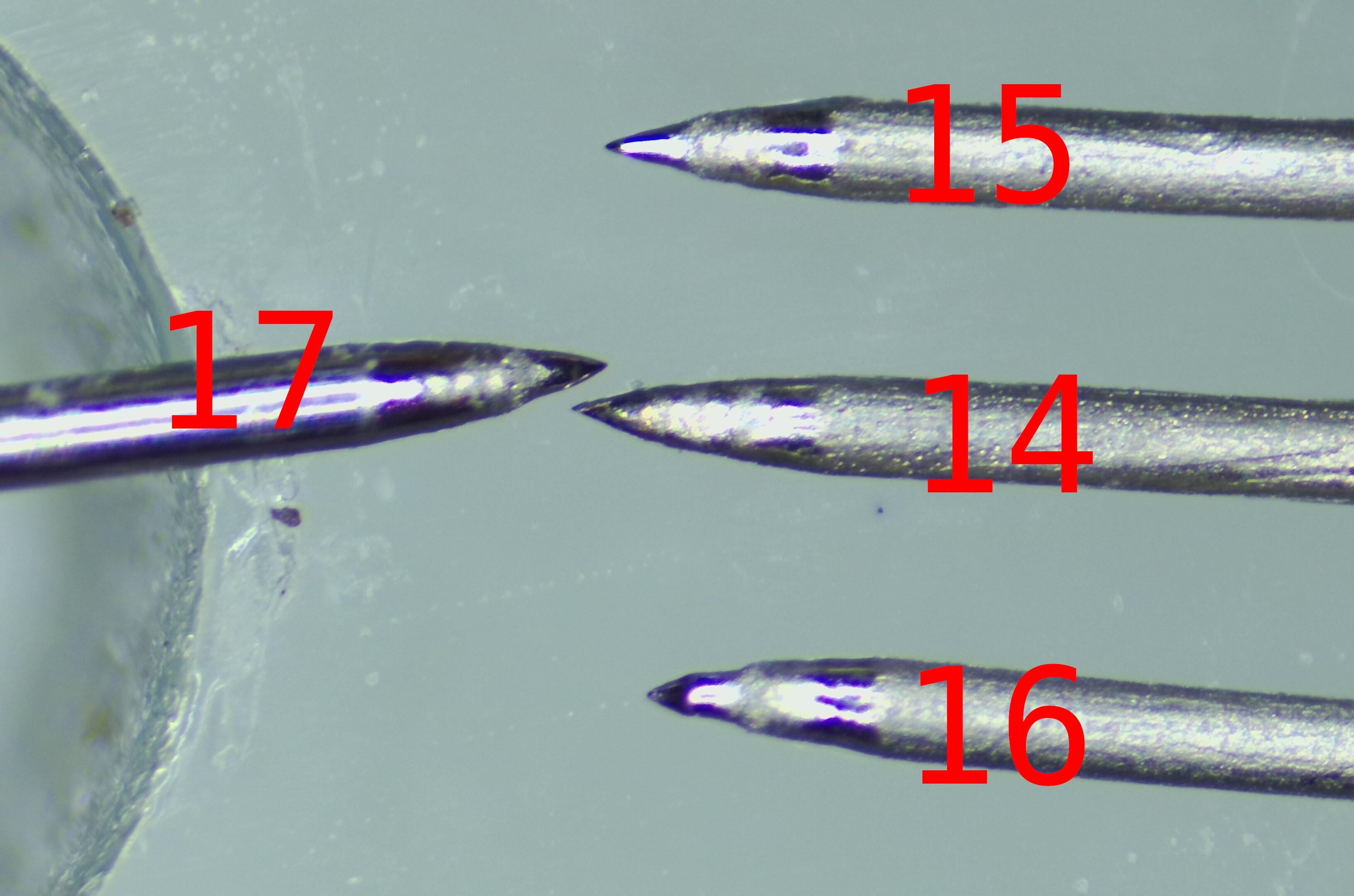
What you should see here is four etched probe tips, numbered, etched from 0.3mm 316L SS wire. #14 was made a couple of days ago before my Z Axis died. That was given a 20 second roughening etch, then the GCODE-controlled etch as per the github repo /utils directory. It has a smooth ogival point.
#15 and #16 were the ones that ended up malformed due to the misbehaving Z Axis. I cut the tips off, and re-etched the wires using the same GCODE as #14. These display a significant stepped profile to the point. Not what I was looking for.
So I wondered. What effect is the roughening etch having on the point profile? So I etched #17 with the same GCODE as #14 but did not do a roughening etch on it. The ogival profile is very good.
All of the probes display a slightly roughened area about 0.1mm behind the tip. This is unplanned but fortuitous. I will experiment with #17 to see if the roughening process is worthwhile when using the sodium chloride etch. The nitric acid roughening etch certainly soaks up the resin, but I have not seen any of this behaviour on the sodium chloride etched tips unless they are over-dipped. Over-dipping is not good for accurate resin deposition as it results in a roughly spherical blob held on the tip by surface tension rather than a film held by capillary action.
Anyhoo, now have tips. Next step is to mount them to the Flexured Probe Holder I printed earlier.
Tuesday, September 08, 2026
Small Square Findings and more breakage, Take 4
I took the Z axis off and followed my own instructions https://github.com/VikOlliver/RepRapMicron/wiki/Probe-Tip-Fabrication-And-Assembly to build three probes. When I started doing the second one, it was pretty obvious something was wrong because I had to raise it much higher above the etchant to break it clear of the meniscus. They came out like this:

Hmm, maybe one is usable but it looks a bit too sharp. After poking around at the Z axis I determined that the locknut at the top of the ZAxis Drive Screw was no longer in the right place. It seemed tight enough. It's possible it released and then re-tightened itself. It's also possible that the Flexure Coupling on the stepper motor has failed or compressed, or that I never had it right to begin with and just got lucky.
Anyway, it is re-tightened. I'll just chop the ends off and try again tomorrow.
I am still not capable of putting more than a couple of hours at a stretch in at the bench I'm afraid. The Doc is pleased with my progress, has upped the painkillers slightly, and - within sensible limits - is allowing me to drive again. So there's improvement somewhere anyway!
Oh, if anyone can donate me any single mode fibre cable, OS1 or OS2 or anything with a 9/125 fibre core or finer, would be appreciated. Why? Well, check out this video of someone else's micro-fabricator: https://youtu.be/UvV2CH5il3Q which is using a fibre to spot-cure resin. Not the approach I wanted to take, but they get more views than me so I have to get with the program and be relevant :) The same arrangement will work just fine on the RepRapMicron.
Monday, September 07, 2026
Probe Flexures With 0.1mm Layer Build
I printed the Probe Flexure with a 0.1mm layer height on the Prusa XL and they came out really nicely. Worth doing in the future.

Still haven't etched the new probe. Thought I'd make a proper set of croc leads with a plug on, got croc clips, Du Pont connectors etc. and then cleverly put a socket on the leads instead of a plug. Arrgh!
Sunday, September 06, 2026
Small Square Findings and wreckage, Take 3
I believe the USB microscope was resetting and misbehaving because everything was plugged into a USB 2.0 hub. I don;t think it could handle two high-res cameras with lights and an Arduino. Something gave. So I have replaced it with a USB 3.0 hub (any donations for my rapidly shrinking personal hardware fund to https://ko-fi.com/viksworkshop ...) and it seems to stay up for 5 mins without flashing the red light at me.
However, as is the way of things at the moment, I broke the flexure probe when fitting the microscope back on and not paying attention:

And so I have to make another one. I'll have to make a new tip as well because I really smacked the point into the slide hard and blunted it:

So that's another hold-up. 'Tis the season, apparently.
Wednesday, September 02, 2026
Small Square, Take 2 ...
This time I'm making the very thing smear on the slide before I put it in the μRepRap. For reasons unknown, the microscope then crashed and flashed it's little LED at me. Reset everything, try again. Problem repeats. Unplug everything, reset everything, try again. Damn.
Okay, microscope is not playing today and prefers to flash status LEDs instead. I'll clean the slide with isopropyl alcohol and an air blast, put the microscope on charge to see if that helps, and try again tomorrow.
