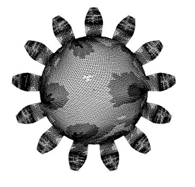
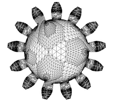
 When I extruded it and exported it as an STL it took 44 megs and had over 100,000 facets (my programme crashed at that point). I then reduced the scale to cm and got this.
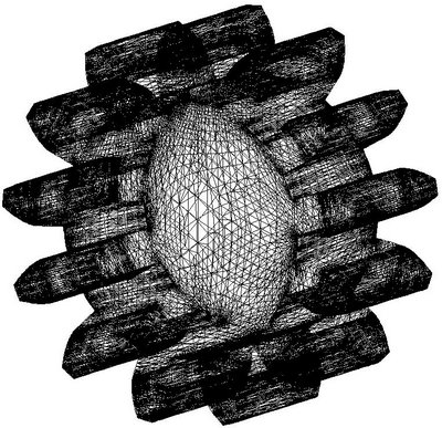
 Which, when extruded and rotated looked like this.
 That little monster had just over 71,000 facets.
Is it just my imagination or could we use a triangle mesh routine that is a little brighter, or perhaps we ought to extend the gear routine to generate itself as an importable OBJ file and mesh it ourselves.
Is this worth doing? Is anybody up to taking on such a Java challenge?
I happen to be a pretty decent Java programmer but I'm a bit out of touch with what you're working on. Not sure how long it'd take for me to get up to speed on this stuff. And there's always the danger that I'll get into it and suddenly be distracted by a pretty redhead. Amazing how often that happens. :^)
ReplyDeleteForrest - I take it we're talking about the AoI triangulation function here.
ReplyDelete***I take it we're talking about the AoI triangulation function here.***
ReplyDeleteYes, we are.
I've been thinking of approaching the problem this way. I wrote up all the logic to do the involute profile gears in VB.NET before I translated it to Java both times that I worked on gears and then racks and pinion gears.
It would be a fairly simple matter for me to rewrite the VB.NET code to design the gear like the Java script does and then do the triangulation right then and spit out a OBJ file which can be imported into AoI where you can extrude it and knock holes in it to reduce polymer mass.
From there it's a very short jump to recompiling the VB.NET code as an ASP.NET web service and put it up on my new web site which runs under Windows Server 2003 or the like.
That way anybody who wanted to design gears would only need a browser and an internet connection.
The point of doing it that way is that I suspect that using a priori knowledge of the way the boundary works on gears I should be able to reduce the number of triangles necessary to fill the boundary by maybe 2-3 magnitudes. That would give a real leg up to folks who are running on Linux and can't access a lot of memory or processing power, like the $100 laptops, for instance.
ReplyDeleteThe heavy lifting would be done on the servers instead of the PC's in kind of a latter day "thin-client" thingy.
Have you tried the AoI "simplify mesh" option to cut down on the number of triangles? Best to do this before extrusion as well as after.
ReplyDeleteVik :v)
***Have you tried the AoI "simplify mesh" option to cut down on the number of triangles? ***
ReplyDeleteYes, I'm glad you mentioned that. I got into the "Edit Object" command and immediately noticed that the mesh shown when you set the display mode to "wire frame" and what you see in the "Edit Object" mode bear little, if any resemblance to each other. The wiremesh mode shows a very, very complicated mesh arrangement while the edit object option shows something crudely simple.
What's with that? When I save as an STL I get something very much like what I see in wire mesh display mode.
Try doing a "Convert to Triangle Mesh" first. That should put it in "what you see is what you get" mode :)
ReplyDeleteVik :v)
Did that. No joy.
ReplyDelete