Sunday, December 26, 2010
Pretty outside, ugly inside
Friday, December 24, 2010
A proper conductive polymer mix?

Thursday, December 16, 2010
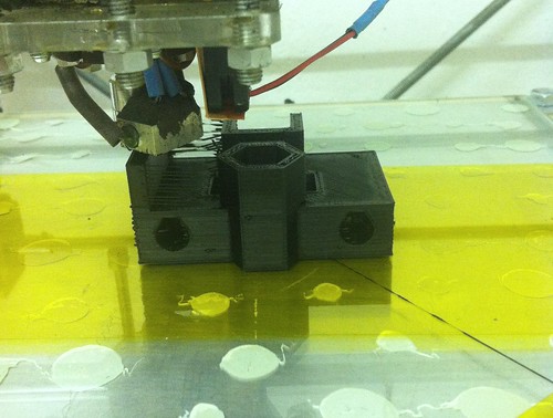
ABS Multicolor Printing

Tuesday, December 14, 2010
Reprappable Inkjet Head

This is an inkjet head that is completely makable in a RepRap machine. It was inspired by Johnrpm's Scratchbuilt_Piezo_Printhead.
It has only three reprapped parts. The other parts are standard easily-obtainable items. There is no machining involved in making it - the only tools needed are scissors, a scalpel or razor blade, a hammer, a short piece of 3 mm steel rod to use as a punch, and a glue gun.
It uses a piezoelectric buzzer to drive the ink.
It is experimental, so it's reliability is not yet perfect... But it does work. Here's the video:
Reprappable inkjet head from Adrian Bowyer on Vimeo.
I need to do more development on the driver electronics. Then I'll see if I can add heater elements so we can inkjet waxes and wood's metal...
Details are on the RepRap Wiki here.
Labels: inkjet, material deposition
Wednesday, December 08, 2010
ReplicatorG for RepRaps: Beta testers wanted
Friday, November 26, 2010
Random thoughts on hot-end design
I spent some time modding the bfb hot-end. Originally the hot end is very sturdy but with extremely soft filament (soft-abs from orbi for example) it is not able to print at low speeds (0.25mm layer 16mm/sec was on the limit, working but not consistent, 0.15mm layer 16mm/sec killed it)...

Labels: hot-end, RapMan, reprap
Wednesday, November 10, 2010
3D printing and "Intellectual Property"
http://www.law.ed.ac.uk/ahrc/script-ed/vol7-1/bradshaw.asp
on the "IP" implications of home 3D printing. This looked at the matter mainly from the UK and EU perspective.
Inspired by that, Public Knowledge, a Washington DC based public interest group, has now put out a white paper on the same questions from a US perspective. You can access it here:
It Will Be Awesome if They Don’t Screw it Up: 3D Printing, Intellectual Property, and the Fight Over the Next Great Disruptive Technology.
Saturday, November 06, 2010
The Gada Prize
These prizes are offered for free and open-source RepRap machines that are significant improvements over the current generation of machines.
To stand a chance of winning you have to register your intention of entering and to publish your developments regularly - we all wanted to make sure that the prizes didn't drive people to develop work in secret, as that would be the exact opposite of what RepRap stands for.
Seventeen teams and individuals have already entered. Entry is free. It is also still open, and will be for quite a while.
So why not have a go!
Wednesday, October 13, 2010
Story of simpler Mendel: Y and Z axes


Monday, October 11, 2010
Replicating laser-cut parts
In which your narrator confects his own idiosyncratic method of replicating laser cut parts.

Do you want to read more?
Monday, October 04, 2010
Story of simpler Mendel: PLA bushings and X-axis

Hello, I'm new here so I guess I should introduce myself first. My name is Josef Prusa, I'm 20 years old student from Prague, Czech republic and I'm in RepRap world for about a year now. You can follow me on http://twitter.com/prusajr.
Also, it makes whole x-carriage snap on to axis rods :-) Its great if you are experimenting with extruders a lot!!


Sunday, September 26, 2010
Dem Bones
In which your narrator creates a way to separate parts from an undifferentiated OBJ file scan of the bones in a human hand.

Do you want to read more?
Friday, September 17, 2010
Dealing with detaching rafts
In which your narrator seems to have come up with a way to prevent raft peel for ABS on an acrylic print table.

Do you want to read more?
Thursday, September 16, 2010
Mendel Drawing

The artist Lauren van Niekerk spend a while in the Bath RepRap Lab recently. One of the things she did was this pen-and-ink drawing of Mendel, which she has given to the project. A 400 dpi scan of it is in the repository here.
Feel free to download it, print it on art paper in your A3 printer, frame it, and hang it on your wall...
Labels: art
Saturday, September 11, 2010
RepRap repraps RepRap electronics

Several people are starting to work on having RepRap make electronics. This includes, of course, making its own circuitry. For example, I'm pleased to say that this blog post itself is rather eclipsed by Johnny Russell's beautifully neat Arduino Mega Shield made in a RepRap here.
I have been integrating PCB production into the RepRap software to try to make it as straightforward as possible. I've used the results to make these:

which you can see fully-assembled at the top of this post. They (together with an Arduino Mega) are a full set or RepRap electronics that you can make in the machine itself. It's all described here.
The software is, needless to say, rather experimental. It is described here. When it's been tested a bit more, we'll do another release with it in. In the meantime, it's all in the latest code in the RepRap Subversion Repository.
Monday, September 06, 2010
Wondering what the fuss is about

Thursday, September 02, 2010
A Smarter Approach to Infill
As is often the case, I had my Mendel running a week or two ago, and I was sat mesmerised for far too long watching it work. Fortunately, whilst this was happening I had an idea I thought was worth sharing.
Our Mendel happened to be printing a particularly complex part, I think it was one of the extruder driven gear. I made the casual observation that on the lower fine layers, it does a pretty good job. But once you get into the middle layers, it needs to do quite a lot more in air movements compared to the fine layers, as the extruder cannot get to where it needs to be smoothly because of the low density of the infill. The issue with this is that with present extruder designs, and even with reversing, we still get some ooze that makes a bit of a mess. Annoyingly, the reversing and inair movements start at the outline of parts, and the ooze typically spills over a tiny amount, making the part surface a little blobby. It also makes sense that this problem is particularly true for intricate areas of the part, such as the gear teeth.
Thus, It would be very beneficial to vary the increase the infill density within the intricate regions of parts. Not only would this help with ooze, but intricate areas would automatically strengthened with more material. I also suspect that if this was implemented we could also reduce the infill percentage in simpler areas to speed up build time.

Fortunately, we already a gauge of part complexity, and that is the length of each individual road within the infill(L) and the distance between infill roads(D) could be made proportional to this length.
Labels: infill
Tuesday, August 31, 2010
RepRap Version III "Huxley"

I've moved the Mini-Mendel page on the Wiki to form a Huxley page here:
http://reprap.org/wiki/Huxley
This is where development of the new machine will be centred. Many people (particularly Erik) have already done a lot of work on Ed's original design.
Please add to their efforts!
Labels: Huxley, RepRap 3, RepRap III
Monday, August 09, 2010
RepRap is going to the NYC Maker Faire!


Sunday, August 08, 2010
Improving print roads calculations
In which your narrator rewrites the Slice and Dice routine that calculates print roads on a slice.
Do you want to read more?
Thursday, August 05, 2010
Reprapping two materials into one object
A couple of days ago, we needed another set of tweezers for the RepRap lab. Naturally, rather than going and buying a pair I thought I'd RepRap them. After a quick search around Thingiverse for inspiration, I thought we could do something a bit more fancy using the new multiple material setup. So I designed the following pair, where the top of the tweezers consists of a PLA inner section for rigidity/stiffness, which is then encased in silicone for added grip, and printed in one shot:

Labels: Multimaterial Tweezers Multiple Materials
Applying VTEC to Slice and Dice
Do you want to read more?
Saturday, July 31, 2010
Towards reprappable electronics
RepRap Mendel with Pololu Electronics from Adrian Bowyer on Vimeo.
A while ago I designed an alternative set of RepRap electronics with the intention that the PCBs required for it would be particularly simple, and hence potentially reprappable. This is the prototype (which I made on stripboard - also easy) working. It's all described here on the wiki, along with a number of other people's versions.The steppers are being micro-stepped (1/16). This makes the whole thing virtually silent, and very smooth in its movement. The firmware supports this new configuration.
Labels: pololu, reprappable electronics
We're Going to the Faire!

Dear readers, the developers of the Michigan RepRap User Group cordially invite one and all to the Detroit Maker Faire!
(Have fun guys!)
Labels: Detroit, Maker Faire, Michigan
Thursday, July 29, 2010
Continuous belt production
I think that (as with so many things) the original idea for this came from Ed Sells. And lots of people have subsequently had ideas of reprapping on a continuous conveyor belt running over a flat surface. See here and here and here.
The big advantage would be that you could print for as long as the plastic filament lasted, continually throwing reprapped parts off the end into a bucket. They would be split from the belt as it ran over the winding roller.
There are two problems that have to be overcome:
- Keeping the belt flat against the tendency of parts to curl away from it, and
- Driving it accurately without slip.
But the second problem is quite easy to solve (usual apologies if someone has though of this before) - you do continuous production without a continuous belt:

By winding and unwinding between two rollers you can cover the entire length of the bed, and pull the part off by running it over the end roller. You can then rewind to print the next part. A simple flag on the belt passing through an opto-switch would allow the system to be zeroed.
Driving the idler roller might require some thought. As the belt winds and unwinds, the roller diameters change, and so does the required velocity ratio between them. The stepper can compensate for this effect by changing the number of steps-per-millimeter it uses depending where it is on the belt to get the build right. But the idler has to do the inverse.
The first thing to say is that - with a thin Kapton film belt - this probably wouldn't matter and you could just run the two rollers with a timing belt between them relying on the elasticity of the system to take up the slack.
But if it did become a problem there are at least three solutions:
- Drive both rollers with steppers. I don't like this as they're bound to end up fighting each other.
- Put a wind-up spring on the idler roller to take up the slack. I'm not too fond of this either. It would probably load the stepper too much, and the forces required from the spring to achieve sudden movements would change with the mass of the object being reprapped.
- Keep a tension on the film by driving the idler clockwise (in the diagram) with a DC motor on a controlled constant current source. Constant current should give constant torque. By changing the current you could compensate for increased mass needing to be moved.
Labels: conveyor belt
Wednesday, July 28, 2010
Some thoughts and observations about having a Reprap machine in the design cycle
In which your narrator reflects on the rather radical difference between what he perceived the design process would be pre and post the advent of practical Reprap printers.
Do you want to read more?
Monday, July 26, 2010
Memories of plastic model airplanes
In which your narrator harks back to his youth and fingerprints ruined by trimming plastic flash off of model airplane parts with double edged razor blades.
Do you want to read more?
Friday, July 23, 2010
Glow-in-the-dark PLA


The phosphor pigment (no actual phosphorous used) needs to be mixed into the plastic at about 10% loading, which is an order of magnitude more than is normally used for colouring. Getting powder to evenly coat the granules at that density is hard, but Alan Booth at Imagin knows a trick or two and it came out beautifully even. The only problem is the cost, which by the time I've got 100m of 3mm filament in a bag is about NZ$60. That's using the cheaper phosphor too - not because I'm cheapskate but because the really good stuff isn't available in quantities of less than a tonne!
Labels: dark, glow, luminous, phosphor, pla
Saturday, July 17, 2010
Mendel & multiple materials
It has always been the intention to fit a head changer to Mendel, I've had a go myself on several occasions but always ran into the same problem i.e. I haven't been able to do so without substantial modifications to the core frame of the machine unless there is a substantial loss of build volume (...I once had a design that ended up having a maximum build height of 2cm.very practical:D). Moreover, it’s more difficult to have a head changer for extruders whose designs are still in the early stages (such as the paste extruder). The main problem I suffered with is that regular designs of extruders are just too bulky without increasing the overall size of the machine, which incidentally I think is the perfect size as it is. Any bigger, and I would find it too big to find houseroom for!
Thankfully, eD had the idea of bowden extruders some time ago, which quite a few people seem have gotten work. Thus I think way forward for the time being is to implement a carriage for multiple bowden style extruders. Although this is almost certainly going to reduce build quality slightly. Some have already designed multiple bowden extruder carriages; here is my take on it:

The main differences are:
1. Support for three extruders, either bowden or paste. (limited syringe size of 10cc).
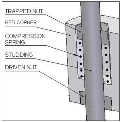
2. All the multiple head machines I've seen rely on the extruders being exactly the same height in order to get the bed clearance just right to produce good builds. I've always found getting adjusting bed clearance is tricky enough just for one extruder, and I think it's likely that there will always be a build up of tolerances that extruder heights will always change by significant magnitudes. Even still, with warping and so on in the carriage, it may still be difficult even if the extruders were identical. Thus, the carriage treats each extruder clearance like pretty much everything else on Mendel, by allowing for adjustment. All extruders are attached to a mounting plate, of which on the underside are of series three captive nuts for each extruder arranged in an equilateral triangle. Three compression springs are then placed between the plate and the extruders, and cap screws are used to adjust the compression of each spring independently. (In the picture above I’ve only used the springs on the left hand extruder, it makes sense to fix the main extruder and adjust the other two to match it)
3. In the same style as the mini carriage, the bearings are all located within the carriage itself. Having the bearings located on the outside surfaces of the carriage( like the standard Mendel design) ensures that the walls of the carriage must lie between the bearings and any extruders, eating into the working volume. However this does result in quite a wide carriage.
4. I needed to make some compromises, neither of which I'm particularly happy with, so that I don’t have to redesign the whole x-axis. Firstly the belt travels through the carriage itself on the 360 side, and secondly the belt is clamped from the inside out.
5. Finally its NOT makerbotable (its about 115 x 95mm), but it should be a fairly easy redesign to allow for only two extruders. . Even still, if you have a RepRap I'd recommend printing in PLA or using a heated bed or you'll probably run into trouble
Anyway, I’ve heavily modified the Paste Extruder, and used it in parallel with a bowden extruder I designed that based on Erik’s design but using a worm gear to do the driving (Designs to be on the SVN/thingiverse shortly). Gerrit Wyen (an intern at the RepRap Lab @ Bath Uni) created a simple script to take account of the offsets between the extruders and modify the GCode accordingly. Also Adrian has done so much I’ve forgotten exactly what he’s done, but its a lot:D. Here is a video one of the first prints; it’s a cube using PLA for the outline and top and bottom layers, and silicone sealant for the interior infill:
Whilst I did reverse the extruder to prevent ooze, and this is sufficient during a "normal build", its sat there for such a long time doing nothing whilst the paste extruder is working it still oozes horribly. For this reason I built little barrier to collect the ooze from hitting the part, but I think we may need to lower the extruder temperature a little when not in use. Anyway, here is the final part, which came out surprisingly well:

There are some more photos of the test setup and some other less successful prints here.
Labels: Bowden Extruder, extruder, multiple materials, paste extruder, x carriage
Friday, July 16, 2010
RepRap in the Year 3000
Here is the homework of Alpha Perry, aged nine. She was asked to imagine herself as a news reporter in the Year 3000, and to write a piece on the history of a technology.
I thought that this was so good (despite its containing bits from me) that I asked her and her parents for permission to add it to the RepRap site...
Labels: school essay
Thursday, July 08, 2010
Overhang support and PCBs

With a lot of work going on on putting pen-plotters in RepRaps for PCBs (and other things), it seemed to me that we might re-visit an old idea.
That idea was using oil to assist separation of support material. Now that the Java host software does full overhang support calculations, it seemed that we might combine the two: a pen plotter with an oil-filled felt pen would run over the top layer of the support after it had been laid down to make it easier to break away when the part was finished.
Above is a brief experiment I did by hand. The L shape was built 'the wrong way up' forcing it to need support. Both the part and it's support were PLA. I paused the build at the last layer of the support deposition, and wiped corn oil over the support with a Q-tip. Then I resumed the build. The support material did indeed separate much more easily than it does without the oil.
If a support layer was simply plotted twice when it was the last support layer under the part, once with the polymer, and then once with an oil-filled felt tip, this would give the same ease of separation. The same pen plotter could be used with an etch-resist pen to make PCBs, such as these designed to make reprappable electronics simple. Two birds; one stone.
Wednesday, July 07, 2010
Vectorization of pixel defined print roads actually working properly
Monday, June 28, 2010
New Release
The host software now runs an awful lot faster when it is slicing RFO files and STL files. This is because I removed something that, in my ignorance, I had thought would make it run faster, but which experimentation has now shown had the opposite effect: I had put a finalize() function in all the geometry classes. That seemed reasonable - give the garbage collector a bit of a hand to tidy things up. But what it actually does is to subvert the garbage collector and to put unreferenced memory into a queue for later removal; a queue that rarely - if ever - seems to get acted upon. If someone can explain why this is a good idea, I'd love to hear it.
Meanwhile, all the finalize() functions are gone, and the host software now runs pretty zippily... (It uses a lot less memory, too.)
The algorithm it uses to find outlines of slices has also been changed to Marching Squares, which seems both more reliable and faster.
The new software now also supports heated beds.
Labels: host software
Monday, June 21, 2010
Vectorization of pixel defined print roads
In which your narrator describes the end, hopefully, of a search for a reasonable way of converting pixel-defined print roads calculated by Slice and Dice.
Do you want to read more?
Sunday, June 20, 2010
Yet another extruder nozzle...

The shortcomings of the standard RepRap extruder have been moaned about (with some justification) on the forums and elsewhere. The PTFE barrel is in tension with the full force of the driven filament. It expands when hot, altering the Z=0 point, and it has the brass extruder nozzle screwed into it; this can tend to come undone, plus the working pressure tends to force the extruded polymer down the thread making and enlarging a gap between the brass and the PTFE.

I have just designed a new one that attempts to combine the benefits of the original design, the very robust Bits from Bytes design, and a number of Nophead's ideas.
There is still a brass barrel and a PTFE insulator. But the PTFE screws inside the brass, so the internal pressure tends to seal the join, rather than opening it up. In addition, all the force is taken by a plate and two pieces of M4 threaded rod, rather than the PTFE. This means that the device keeps its Z=0 point. Not counting M4 nuts, it has six parts (there's a PEEK top-hat separator between the plate and the brass - you can see that in the top picture, but not in the exploded view).
Final advantages are that it's much easier to take apart and to put back together, and you don't have to wait for glue to set before using it.
All details will be here on the wiki soon.
Wednesday, June 16, 2010
Reprap Aggregation Pipe - V2 update

Hi All,
I just wanted to let you all know that the Reprap "Blog of Blogs" has just been upgraded to use the new Yahoo "V2" pipes technology! (today)
For those that live under a rock ( or are new) this is the URL for the meta-blog of around 100 reprap blogs:
http://pipes.yahoo.com/davidbuzz/reprap_aggregation_pipe
..and this is a brief from Yahoo on the new technology, which went into BETA about a week ago.
http://blog.pipes.yahoo.net/2010/06/09/yahoo-pipes-v2-engine/
Happy Blogging!
Buzz.
Thursday, June 10, 2010
Inkjet RepRap

A while ago Amberish Jaipuria did some preliminary RepRap experiments with inkjets - details are here. And before he left, Ed was always saying, "I think inkjet is the way to go."
It would certainly be nice to be able to lay down waxes, resins, conducting ink and all the rest in a RepRap with the fineness and precision that inkjet could give. We would probably want to use Epson inkjets, which use piezoelectric mechanical pulses to eject the ink drops. All the other systems boil the ink by resistive heating in a tiny chamber to eject it. The piezoelectric systems will obviously be more tolerant of funny polymers and the like, which might not take kindly to being boiled.
Recently I have been looking at continuous ink systems. These replace the normal (and horribly expensive) inkjet cartridges with a tank-fed system that holds 100 ml or more. And they're cheap - the four above cost me £13 in total including postage from these people. You get the tanks, the feed tubes and the hacked recycled cartridges for that. I say hacked, because the cartridges are chipped to report emptiness to the printer - this is how the manufacturers try to prevent you doing re-fills. These report "full" all the time, I think.
Now, with an Epson, the piezoelectric heads are not in the cartridge (it's just an ink reservoir). They are built into the printer. There's a good article about all this by Tim Hunkin here. (Note especially the bit about Epson heads clogging if you leave them unused or let airlocks get in.)
So to the $64,000 question: I have done a good bit of searching for the electronic incantations that need to be sent to the piezoelectric heads taken out of an old Epson printer, and I have drawn a blank. What's needed is the Epson equivalent of this excellent HP Inkjet book by Matt Gililland. I could prod about in the printer with a scope, of course, but it would be nice to have something authoritative.
Does anyone know what pulse-timing patterns and voltages Epson piezoelectric heads need?
Labels: inkjet material deposition
Saturday, May 29, 2010
Major New Scientist RepRap Article

The New Scientist is running a feature article by Tom Simonite on RepRap and its derivatives this week. Tom visited the RepRap Lab at Bath University, the London Hackspace and other places a few weeks ago to research his article.
To read it, go to this link.
Labels: press
Tuesday, May 25, 2010
RepRap Talk - Bogota
Details are at: http://www.campus-party.com.co/Software_Libre.html
Labels: talks
Saturday, May 22, 2010
Mendel Variations and Lasers!!!
This one is particularly significant.

LaserCut_Mendel by Kimberly and Lambert Andrus of TechZoneCommunications.com llc.
LaserCut Mendel has the same metal hardware and other paraphernalia as vanilla Mendel. But now you can make one in the privacy of your own home using your laser cutter!!! (If you don't happen to have a laser cutter, you can buy a LaserCut Mendel from Kimberly in the RepRap For Sale Forum, or come out this weekend to the Bay Area Maker Faire, and buy one from her in person).
Kimberly Anders also sells a version of the RepRap Gen 3 Electronics, the Generation_3_Electronics - Tech_Zone_Remix. These boards have generated quite a bit of interest in the community and you can buy them in this thread in The RepRap For Sale Forum. In the best RepRap traditions, our fellow users are helping document them here: Generation_3_Electronics/Tech_Zone_Remix/How_to. (Discussion/Support)
Labels: generation 3 electronics, lasercutter, Mendel, techzone
Thursday, May 20, 2010
An Open-Source Scanning Tunneling Microscope

Yesterday I ran into Jochen Klingelhoefer of Lab Minds. He introduced me to the SXM Project - a project to distribute an open-source scanning tunneling microscope (already working) and a scanning force microscope (under development).
How cool is that? Many of the parts are eminently reprappable too.
For details follow this link.
Just to whet your appetite, here is a picture of a 4 nm square area on the surface of a piece of graphite made with the microscope:

Note the atoms...
Labels: scanning tunneling microscope
Saturday, May 15, 2010
Quick hot bed temperature controller...

I do not have a SSR lying around but I have bunch of "no name / no marking" 25A 600V triac's that are perfect for the job, I used the MOC3043 (optocoupler with triak output and zero crossing detection) to separate the electronics from the AC going in to heat bed (I'm using 41VAC), the microchip PIC16F819 is used to drive the LCD, read NTC and work as I2C slave. NTC is connected with 10K resistor to maximize reading range between 20 and 180C. NTC used is same one from BFB hot end's (GT-204).
Source (PICC C file) is available here.
Labels: controller, heated bed, I2C, Mendel, PIC, RapMan
Wednesday, May 12, 2010
A Heated Bed for Mendel
I thought I'd have a go too. Instead of the TO220 resistors he used, I used nichrome wire taped down with Kapton on the back.
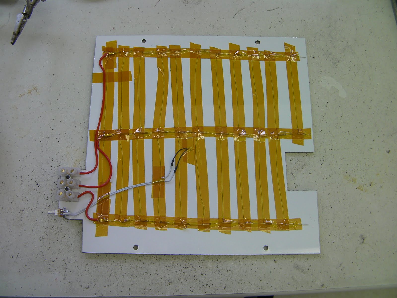
Then I insulated that with crack-filler foam, cut down to about 10mm thick with a bread knife.

It seems to work well. Here are the larger Mendel parts printed on it in PLA with it set to 50oC. Their bottoms are f. as pancakes.

I used a piece of ordinary aluminium sheet clipped on the top with bulldog clips to give me a removable tray with good thermal conductivity. That is what has the blue tape on here. The tray is flexible, but the Dibond holds it flat.
I thought it'd be clever to use the 5v supply out of my PC PSU, as that's not being used for anything else. But the current (16A) is a bit silly - connectors and so on get warmish. For the next one I'll run it at 12v and about 7A.
Dibond is rated up to 80oC, which means it's fine for PLA, but might not get hot enough for ABS.
I've integrated it into the host software, the G Codes, and the firmware and updated the copies in the repository. I have to go to Cardiff tomorrow to give a RepRap talk to the British Computer Society, but I hope to put all the details on the wiki over the weekend.
Labels: dibond, heated bed, Mendel
Sunday, May 02, 2010
Board Supports

I got irritated by the thought of a large chunk of wood that could be replaced by printing. So I'm tinkering with these modular panels about 100mm a side, scaled to fit the frame 3 abreast using the same fittings as their wooden counterpart.
Here you can see an Arduino with a simple prototype board on it. This holds 2 of TIP122 drivers for the heater and an experimental DC extruder. Alternatively it can hold 2 EasyDriver stepper controllers. Basic, but hopefully reliable.
 They interconnect with 2xM4 16mm screws and trapped nuts. Objects can be anchored on pillars with 40mm M3 or M4 screws, or against the module's surface with 30mm ones. Here are some preliminary prototypes. I've attached them to the current "Simplified Kiwi Mendel" known more affectionately as Lemon Slice.
Speaking of slices, I caught my hand on a falling mandoline and have to rest my left hand. fortunately thumb works so I can sneakily enter blogs from bed on my phone...
Vik :v)
Labels: kiwi, mandoline, Mendel, module, panel, printed, reprap
![]()